Internet protocols#
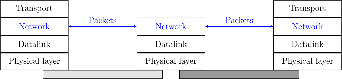
The main objective of the network layer is to allow hosts, connected to different networks, to exchange information through intermediate systems called router. The unit of information in the network layer is called a packet.
Fig. 106 The network layer in the reference model
Before explaining the network layer in detail, it is useful to begin by analyzing the service provided by the datalink layer. There are many variants of the datalink layer. Some provide a connection-oriented service while others provide a connectionless service. In this section, we focus on connectionless datalink layer services as they are the most widely used. Using a connection-oriented datalink layer causes some problems that are beyond the scope of this chapter. See RFC 3819 for a discussion on this topic.
Fig. 107 The point-to-point datalink layer
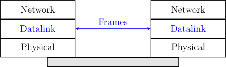
There are three main types of datalink layers. The simplest datalink layer is when there are only two communicating systems that are directly connected through the physical layer. Such a datalink layer is used when there is a point-to-point link between the two communicating systems. The two systems can be hosts or routers. PPP, defined in RFC 1661, is an example of such a point-to-point datalink layer. Datalink layers exchange frames and a datalink frame sent by a datalink layer entity on the left is transmitted through the physical layer, so that it can reach the datalink layer entity on the right. Point-to-point datalink layers can either provide an unreliable service (frames can be corrupted or lost) or a reliable service (in this case, the datalink layer includes retransmission mechanisms similar to the ones used in the transport layer). The unreliable service is frequently used above physical layers (e.g. optical fiber, twisted pairs) having a low bit error ratio while reliability mechanisms are often used in wireless networks to recover locally from transmission errors.
The second type of datalink layer is the one used in Local Area Networks (LAN). Conceptually, a LAN is a set of communicating devices such that any two devices can directly exchange frames through the datalink layer. Both hosts and routers can be connected to a LAN. Some LANs only connect a few devices, but there are LANs that can connect hundreds or even thousands of devices.
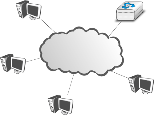
Fig. 108 A local area network#
In the second part, we describe the organization and the operation of Local Area Networks. An important difference between the point-to-point datalink layers and the datalink layers used in LANs is that in a LAN, each communicating device is identified by a unique datalink layer address. This address is usually embedded in the hardware of the device and different types of LANs use different types of datalink layer addresses. Most LANs use 48-bits long addresses that are usually called MAC addresses. A communicating device attached to a LAN can send a datalink frame to any other communicating device that is attached to the same LAN. Most LANs also support special broadcast and multicast datalink layer addresses. A frame sent to the broadcast address of the LAN is delivered to all communicating devices that are attached to the LAN. The multicast addresses are used to identify groups of communicating devices. When a frame is sent towards a multicast datalink layer address, it is delivered by the LAN to all communicating devices that belong to the corresponding group.
The third type of datalink layers are used in Non-Broadcast Multi-Access (NBMA) networks. These networks are used to interconnect devices like a LAN. All devices attached to an NBMA network are identified by a unique datalink layer address. However, and this is the main difference between an NBMA network and a traditional LAN, the NBMA service only supports unicast. The datalink layer service provided by an NBMA network supports neither broadcast nor multicast.
Unfortunately no datalink layer is able to send frames of unlimited size. Each datalink layer is characterized by a maximum frame size. There are more than a dozen different datalink layers and unfortunately most of them use a different maximum frame size. The network layer must cope with the heterogeneity of the datalink layer.
Two different network layer protocols coexist on the Internet: IP version 4 and IP version 6. As explained earlier, these two protocols allow a host to send packets to any other host. Both protocols support variable-length packets. The most important difference between IPv4 and IPv6 is the size of the IP addresses. IPv4 uses addresses that are encoded as a 32 bits long (4 bytes) bit string. IPv6 addresses are much longer. An IPv6 address is encoded as a 128 bits long (16 bytes) bit string.
In this section, we describe how hosts use these two protocols to send and receive packets. We do not discuss how IP addresses are allocated and how IP packets can be efficiently forwarded through the Internet. These parts of IPv4 and IPv6 are discussed in the second part of the book.
IP version 4#
IP version 4 is the data plane protocol of the network layer in the TCP/IP protocol suite. The design of IP version 4 was based on the following assumptions :
IP should provide an unreliable connectionless service (TCP provides reliability when required by the application)
IP operates with the datagram transmission mode
IP addresses have a fixed size of 32 bits
IP must be usable above different types of datalink layers
IP hosts exchange variable length packets
IPv4 addresses are encoded as a 32 bits field. IPv4 addresses are often represented in dotted-decimal format as a sequence of four integers separated by a dot. The first integer is the decimal representation of the most significant byte of the 32 bits IPv4 address, … For example,
1.2.3.4 corresponds to 00000001000000100000001100000100
127.0.0.1 corresponds to 01111111000000000000000000000001
255.255.255.255 corresponds to 11111111111111111111111111111111
An IPv4 address is used to identify an interface on a router or a host. A router has thus as many IPv4 addresses as the number of interfaces that it has in the datalink layer. Most hosts have a single datalink layer interface and thus have a single IPv4 address. However, with the growth of wireless, more and more hosts have several datalink layer interfaces (e.g. an Ethernet interface and a WiFi interface). These hosts are said to be multihomed. A multihomed host with two interfaces has thus two IPv4 addresses.
Many Internet hosts are attached to Local Area Networks (LANs) such as Wi-Fi or Ethernet networks. We will describe the operation of these networks in more details in the second part of the book, but at this stage, the important point to know about these LANs is that they provide a connectionless datalink layer service. On a LAN, each device is identified by a unique 48 bits long address that is called a MAC address (MAC stands for Medium Access Control that will be explained in details in the second part). To ensure the unicity of the MAC addresses, these addresses are usually hardwired directly on the network interface cards. Each vendor of network cards ensures that all the interfaces that it sells have a unique MAC address. The devices attached a LAN can exchanged frames easily. A frame is a sequence of bytes that starts with a fixed-length header followed by a payload and for some types of LANs a trailer. The frame header contains the MAC address of the source of the frame and the MAC address of the destination of the frame. The frame payload carries the information exchanged and the trailer can contain a CRC to detect transmission errors or other types of control information.

Fig. 109 A datalink layer frame containing an IPv4 packet#
When several hosts are attached to the same LAN, they can quickly exchange IP packets by placing these packets inside datalink layer frames. If host A knows the MAC address of host B, it can send an IP packet as the payload of a frame whose source MAC address is its own MAC address and destination MAC address is B’s MAC address. We will detail later how a host can automatically learn the MAC address of another host.
When a host is attached to a LAN, it can directly send packets to the other hosts attached to the same LAN. To reach remote hosts, it must first send its packets to a router, also attached to the LAN. The router will be able to forward the packet to other routers such that it reaches its final destination.
When a host attached to a LAN sends an IP packet, it needs to know whether the destination is attached to the same LAN or not. If the destination is attached to the same LAN, the host can simply place the packet inside a frame and us the datalink layer to deliver it directly to its final destination. Otherwise, the host must the datalink layer to send the packet inside a frame to the LAN router that will take care of the packet. IPv4 and IPv6 solve this problem by grouping IP addresses in subnets. An IP subnet is the set of all IP addresses that have the same prefix. It is represented as an IP address followed by n, the number of bits in the common prefix.
An IPv4 address is composed of two parts : a subnetwork identifier and a host identifier. The subnetwork identifier is composed of the high order bits of the address and the host identifier is encoded in the low order bits of the address. This is illustrated below with a 22 bits subnetwork identifier shown in blue and a 12 bits host identifier in red.

Fig. 110 The subnetwork (blue) and host identifiers (red) inside an IPv4 address
A subnet identifier or IPv4 prefix is usually [1] represented as A.B.C.D/p where A.B.C.D is the network address obtained by concatenating the subnet identifier with a host identifier containing only 0 and p is the length of the subnet identifier in bits. The table below provides examples of IP subnets.
Subnet |
Number of addresses |
Smallest address |
Highest address |
|---|---|---|---|
10.0.0.0/8 |
16,777,216 |
10.0.0.0 |
10.255.255.255 |
192.168.0.0/16 |
65,536 |
192.168.0.0 |
192.168.255.255 |
198.18.0.0/15 |
131,072 |
198.18.0.0 |
198.19.255.255 |
192.0.2.0/24 |
256 |
192.0.2.0 |
192.0.2.255 |
10.0.0.0/30 |
4 |
10.0.0.0 |
10.0.0.3 |
10.0.0.0/31 |
2 |
10.0.0.0 |
10.0.0.1 |
Note
Class A, B, or C addresses
Today’s IPv4 implementations use variable-length subnets defined in RFC 1519. With variable-length subnets, the subnet identifier can be any size, from 1 to 31 bits. Variable-length subnets allow the network operators to use a subnet that better matches the number of hosts that are placed inside the subnet. Before the publication of RFC 1519, IPv4 address blocks were divided in classes of addresses. RFC 791 defined three classes of IPv4 addresses depending on their high order bits:
Class A addresses are the addresses whose high order bit is set to zero. The high order byte of this address was the network identifier and the 24 low order bits the host identifier. They correspond to today’s
\8subnets.Class B addresses are the addresses whose two high order bits are set to one followed by zero. The next fourteen bits are the network identifier and the low order sixteen bits the host identifier. They correspond to today’s
/16subnets.Class C addresses are the addresses whose three high order bits are set to one followed by one and then zero. The next fourteen bits are the network identifier and the low order twenty four bits the host identifier. They correspond to today’s
/24subnets.
Initially, address blocks were allocated based on the address class required. Large companies, network providers and some universities asked for a Class A addresses and obtained it. Many universities requested a Class B address. However, this allocation was inefficient as Class A address blocks are much larger than the needs of most enterprises while Class C are too small. RFC 1519 suppressed this inefficient allocation. Nowadays, the IPv4 addressing space is almost fully utilized, except some reserved blocks. The IPv4 Address Report provides a detailed report on the evolution of the allocated IPv4 addressing space.
Note
Special IPv4 addresses
Most unicast IPv4 addresses can appear as source and destination addresses in packets on the global Internet. However, it is worth noting that some blocks of IPv4 addresses have a special usage, as described in RFC 5735. These include :
0.0.0.0/8, which is reserved for self-identification. A common address in this block is 0.0.0.0, which is sometimes used when a host boots and does not yet know its IPv4 address.
127.0.0.0/8, which is reserved for loopback addresses. Each host implementing IPv4 must have a loopback interface (that is not attached to a datalink layer). By convention, IPv4 address 127.0.0.1 is assigned to this interface. This allows processes running on a host to use TCP/IP to contact other processes running on the same host. This can be very useful for testing purposes.
10.0.0.0/8, 172.16.0.0/12 and 192.168.0.0/16 are reserved for private networks that are not directly attached to the Internet. These addresses are often called private addresses or RFC 1918 addresses.
169.254.0.0/16 is used for link-local addresses RFC 3927. Some hosts use an address in this block when they are connected to a network that does not allocate addresses as expected.
IPv4 packets#
The IPv4 packet format was defined in RFC 791. It is shown in Fig. 111. Apart from a few clarifications and some backward compatible changes, the IPv4 packet format did not change significantly since the publication of RFC 791. All IPv4 packets use the 20 bytes header shown in figure Fig. 111. Some IPv4 packets contain an optional header extension that is described later.

Fig. 111 The IP version 4 header#
The main fields of the IPv4 header are :
a 4 bits version that indicates the version of IP used to build the header. Using a version field in the header allows the network layer protocol to evolve.
a 4 bits IP Header Length (IHL) that indicates the length of the IP header in 32 bits words. This field allows IPv4 to use options if required, but as it is encoded as a 4 bits field, the IPv4 header cannot be longer than 64 bytes.
an 8 bits DS field that is used for Quality of Service and whose usage is described later.
an 8 bits Protocol field that indicates the transport layer protocol that must process the packet’s payload at the destination. Common values for this field [2] are 6 for TCP and 17 for UDP
a 16 bits length field that indicates the total length of the entire IPv4 packet (header and payload) in bytes. This implies that an IPv4 packet cannot be longer than 65535 bytes.
a 32 bits source address field that contains the IPv4 address of the source host
a 32 bits destination address field that contains the IPv4 address of the destination host
a 16 bits checksum that protects only the IPv4 header against transmission errors
The other fields of the IPv4 header are used for specific purposes. The first is the 8 bits Time To Live (TTL) field. This field is used by IPv4 to avoid the risk of having an IPv4 packet caught in an infinite loop due to a transient or permanent error in routing tables [3]. We will discuss in part two why such problems can happen. The TTL field of the IPv4 header ensures that even if there are forwarding loops in the network, packets will not loop forever. Hosts send their IPv4 packets with a positive TTL (usually 64 or more [4]). When a router receives an IPv4 packet, it first decrements the TTL by one. If the TTL becomes 0, the packet is discarded and a message is sent back to the packet’s source (see section ICMP). Otherwise, the router performs a lookup in its forwarding table to forward the packet.
A second problem for IPv4 is the heterogeneity of the datalink layer. IPv4 is used above many very different datalink layers. Each datalink layer has its own characteristics and as indicated earlier, each datalink layer is characterized by a maximum frame size. From IP’s point of view, a datalink layer interface is characterized by its Maximum Transmission Unit (MTU). The MTU of an interface is the largest IPv4 packet (including header) that it can send. The table below provides some common MTU sizes [5].
Datalink layer |
MTU |
Ethernet |
1500 bytes |
WiFi |
2272 bytes |
ATM (AAL5) |
9180 bytes |
802.15.4 |
102 or 81 bytes |
Token Ring |
4464 bytes |
FDDI |
4352 bytes |
Although an IPv4 host can theoretically send 64 KBytes long packets, few datalink layer technologies that are used today are able to send a 64 KBytes IPv4 packet inside a frame. Consider a client attached to a Token Ring network that wishes to send packets to a server connected to an Ethernet network. The client could send a 4 KBytes packet that would need to be fragmented inside the network to reach the server.
To solve these problems, IPv4 includes a packet fragmentation and reassembly mechanism. Both hosts and intermediate routers may fragment an IPv4 packet if the packet is too long to be sent via the datalink layer. In IPv4, fragmentation is completely performed in the IP layer and a large IPv4 is fragmented into two or more IPv4 packets (called fragments). The IPv4 fragments of a large packet are normal IPv4 packets that are forwarded towards the destination of the large packet by intermediate routers.
The IPv4 fragmentation mechanism relies on four fields of the IPv4 header : Length, Identification, the flags and the Fragment Offset. The IPv4 header contains two flags : More fragments and Don’t Fragment (DF). When the DF flag is set, this indicates that the packet cannot be fragmented.
The basic operation of the IPv4 fragmentation is as follows. A large packet is fragmented into two or more fragments. The size of all fragments, except the last one, is equal to the Maximum Transmission Unit of the link used to forward the packet. Each IPv4 packet contains a 16 bits Identification field. When a packet is fragmented, the Identification of the large packet is copied in all fragments to allow the destination to reassemble the received fragments together. In each fragment, the Fragment Offset indicates, in units of 8 bytes, the position of the payload of the fragment in the payload of the original packet. The Length field in each fragment indicates the length of the payload of the fragment as in a normal IPv4 packet. Finally, the More fragments flag is set only in the last fragment of a large packet.
The following pseudo-code details the IPv4 fragmentation algorithm, assuming that the packet does not contain IP options.
#mtu : maximum size of the packet (including header) of outgoing link
if p.len <  mtu :
 send(p)
# packet is too large
maxpayload=8*int((mtu-20)/8)  # must be n times 8 bytes
if p.flags=='DF' :
 discard(p)
# packet must be fragmented
payload=p[IP].payload
pos=0
while len(payload) > 0 :
 if len(payload) > maxpayload :
    toSend=IP(dest=p.dest,src=p.src,
              ttl=p.ttl, id=p.id,
              frag=p.frag+(pos/8),
              len=mtu, proto=p.proto)/payload[0:maxpayload]
    pos=pos+maxpayload
    payload=payload[maxpayload+1:]
 else
    toSend=IP(dest=p.dest,src=p.src,
              ttl=p.ttl, id=p.id,
              frag=p.frag+(pos/8),
              flags=p.flags,
              len=len(payload), proto=p.proto)/payload
 forward(toSend)
The fragments of an IPv4 packet may arrive at the destination in any order, as each fragment is forwarded independently in the network and may follow different paths. Furthermore, some fragments may be lost and never reach the destination.
The reassembly algorithm used by the destination host is roughly as follows. First, the destination can verify whether a received IPv4 packet is a fragment or not by checking the value of the More fragments flag and the Fragment Offset. If the Fragment Offset is set to 0 and the More fragments flag is reset, the received packet has not been fragmented. Otherwise, the packet has been fragmented and must be reassembled. The reassembly algorithm relies on the Identification field of the received fragments to associate a fragment with the corresponding packet being reassembled. Furthermore, the Fragment Offset field indicates the position of the fragment payload in the original non fragmented packet. Finally, the packet with the More fragments flag reset allows the destination to determine the total length of the original no fragmented packet.
Note that the reassembly algorithm must deal with the unreliability of the IP network. This implies that a fragment may be duplicated or a fragment may never reach the destination. The destination can easily detect fragment duplication thanks to the Fragment Offset. To deal with fragment losses, the reassembly algorithm must bound the time during which the fragments of a packet are stored in its buffer while the packet is being reassembled. This can be implemented by starting a timer when the first fragment of a packet is received. If the packet has not been reassembled upon expiration of the timer, all fragments are discarded and the packet is considered to be lost.
The original IP specification, in RFC 791, defined several types of options that can be added to the IP header. Each option is encoded using a type length value format. They are not widely used today. Additional details may be found in RFC 791.
ICMP version 4#
It is sometimes necessary for intermediate routers or the destination host to inform the sender of the packet of a problem that occurred while processing a packet. In the TCP/IP protocol suite, this reporting is done by the Internet Control Message Protocol (ICMP). ICMP is defined in RFC 792. ICMP messages are carried as the payload of IP packets (the protocol value reserved for ICMP is 1). Fig. 112 illustrates the IPv4 header. An ICMP message is composed of an 8 byte header and a variable length payload that usually contains the first bytes of the packet that triggered the transmission of the ICMP message.

In the ICMP header, the Type and Code fields indicate the type of problem that was detected by the sender of the ICMP message. The Checksum protects the entire ICMP message against transmission errors and the Data field contains additional information for some ICMP messages.
The main types of ICMP messages are :
Destination unreachable : a Destination unreachable ICMP message is sent when a packet cannot be delivered to its destination due to routing problems. Different types of non reachability are distinguished :
Network unreachable : this ICMP message is sent by a router that does not have a route for the subnet containing the destination address of the packet
Host unreachable : this ICMP message is sent by a router that is attached to the subnet that contains the destination address of the packet, but this destination address cannot be reached at this time
Protocol unreachable : this ICMP message is sent by a destination host that has received a packet, but does not support the transport protocol indicated in the packet’s Protocol field
Port unreachable : this ICMP message is sent by a destination host that has received a packet destined to a port number, but no server process is bound to this port
Fragmentation needed : this ICMP message is sent by a router that receives a packet with the Don’t Fragment flag set that is larger than the MTU of the outgoing interface
ping(8) is often used by network operators to verify that a given IP address is reachable. Each host is supposed [6] to reply with an ICMP Echo reply message when its receives an ICMP Echo request message. A sample usage of ping(8) is shown below.
ping 130.104.1.1
PING 130.104.1.1 (130.104.1.1): 56 data bytes
64 bytes from 130.104.1.1: icmp_seq=0 ttl=243 time=19.961 ms
64 bytes from 130.104.1.1: icmp_seq=1 ttl=243 time=22.072 ms
64 bytes from 130.104.1.1: icmp_seq=2 ttl=243 time=23.064 ms
64 bytes from 130.104.1.1: icmp_seq=3 ttl=243 time=20.026 ms
64 bytes from 130.104.1.1: icmp_seq=4 ttl=243 time=25.099 ms
--- 130.104.1.1 ping statistics ---
5 packets transmitted, 5 packets received, 0% packet loss
round-trip min/avg/max/stddev = 19.961/22.044/25.099/1.938 ms
Another very useful debugging tool is traceroute(8). The traceroute man page describes this tool as “print the route packets take to network host”. traceroute uses the TTL exceeded ICMP messages to discover the intermediate routers on the path towards a destination. The principle behind traceroute is very simple. When a router receives an IP packet whose TTL is set to 1 it decrements the TTL and is forced to return to the sending host a TTL exceeded ICMP message containing the header and the first bytes of the discarded IP packet. To discover all routers on a network path, a simple solution is to first send a packet whose TTL is set to 1, then a packet whose TTL is set to 2, etc. A sample traceroute output is shown below.
traceroute www.ietf.org
traceroute to www.ietf.org (64.170.98.32), 64 hops max, 40 byte packets
 1  CsHalles3.sri.ucl.ac.be (192.168.251.230)  5.376 ms  1.217 ms  1.137 ms
 2  CtHalles.sri.ucl.ac.be (192.168.251.229)  1.444 ms  1.669 ms  1.301 ms
 3  CtPythagore.sri.ucl.ac.be (130.104.254.230)  1.950 ms  4.688 ms  1.319 ms
 4  fe.m20.access.lln.belnet.net (193.191.11.9)  1.578 ms  1.272 ms  1.259 ms
 5  10ge.cr2.brueve.belnet.net (193.191.16.22)  5.461 ms  4.241 ms  4.162 ms
 6  212.3.237.13 (212.3.237.13)  5.347 ms  4.544 ms  4.285 ms
 7  ae-11-11.car1.Brussels1.Level3.net (4.69.136.249)  5.195 ms  4.304 ms  4.329 ms
 8  ae-6-6.ebr1.London1.Level3.net (4.69.136.246)  8.892 ms  8.980 ms  8.830 ms
 9  ae-100-100.ebr2.London1.Level3.net (4.69.141.166)  8.925 ms  8.950 ms  9.006 ms
 10  ae-41-41.ebr1.NewYork1.Level3.net (4.69.137.66)  79.590 ms
     ae-43-43.ebr1.NewYork1.Level3.net (4.69.137.74)  78.140 ms
     ae-42-42.ebr1.NewYork1.Level3.net (4.69.137.70)  77.663 ms
 11  ae-2-2.ebr1.Newark1.Level3.net (4.69.132.98)  78.290 ms  83.765 ms  90.006 ms
 12  ae-14-51.car4.Newark1.Level3.net (4.68.99.8)  78.309 ms  78.257 ms  79.709 ms
 13  ex1-tg2-0.eqnwnj.sbcglobal.net (151.164.89.249)  78.460 ms  78.452 ms  78.292 ms
 14  151.164.95.190 (151.164.95.190)  157.198 ms  160.767 ms  159.898 ms
 15  ded-p10-0.pltn13.sbcglobal.net (151.164.191.243)  161.872 ms  156.996 ms  159.425 ms
 16  AMS-1152322.cust-rtr.swbell.net (75.61.192.10)  158.735 ms  158.485 ms  158.588 ms
 17  mail.ietf.org (64.170.98.32)  158.427 ms  158.502 ms  158.567 ms
The above traceroute(8) output shows a 17 hops path between a host at UCLouvain and one of the main IETF servers. For each hop, traceroute provides the IPv4 address of the router that sent the ICMP message and the measured round-trip-time between the source and this router. traceroute sends three probes with each TTL value. In some cases, such as at the tenth hop above, the ICMP messages may be received from different addresses. This is usually because different packets from the same source have followed different paths [7] in the network.
Another important utilization of ICMP messages is to discover the maximum MTU that can be used to reach a destination without fragmentation. As explained earlier, when an IPv4 router receives a packet that is larger than the MTU of the outgoing link, it must fragment the packet. Unfortunately, fragmentation is a complex operation and routers cannot perform it at line rate [KM1995]. Furthermore, when a TCP segment is transported in an IP packet that is fragmented in the network, the loss of a single fragment forces TCP to retransmit the entire segment (and thus all the fragments). If TCP was able to send only packets that do not require fragmentation in the network, it could retransmit only the information that was lost in the network. In addition, IP reassembly causes several challenges at high speed as discussed in RFC 4963. Using IP fragmentation to allow UDP applications to exchange large messages raises several security issues [KPS2003].
ICMP, combined with the Don’t fragment (DF) IPv4 flag, is used by TCP implementations to discover the largest MTU size that is allowed to reach a destination host without causing network fragmentation. This is the Path MTU discovery mechanism defined in RFC 1191. A TCP implementation that includes Path MTU discovery (most do) requests the IPv4 layer to send all segments inside IPv4 packets having the DF flag set. This prohibits intermediate routers from fragmenting these packets. If a router needs to forward a packet which cannot be fragmented over a link with a smaller MTU, it returns a Fragmentation needed ICMP message to the source, indicating the MTU of its outgoing link. This ICMP message contains in the MTU of the router’s outgoing link in its Data field. Upon reception of this ICMP message, the source TCP implementation adjusts its Maximum Segment Size (MSS) so that the packets containing the segments that it sends can be forwarded by this router without requiring fragmentation.
Operation of IPv4 hosts#
At this point of the description of IPv4, it is useful to have a detailed look at how an IPv4 implementation sends, receives and forwards IPv4 packets. The simplest case is when a host needs to send a segment in an IPv4 packet. The host performs two operations. First, it must decide on which interface the packet will be sent. Second it must create the corresponding IP packet(s).
To simplify the discussion in this section, we ignore the utilization of IPv4 options. This is not a severe limitation as today IPv4 packets rarely contain options. Details about the processing of the IPv4 options may be found in the relevant RFCs, such as RFC 791.
An IPv4 host having \(n\) datalink layer interfaces manages \(n+1\) IPv4 addresses :
the 127.0.0.1/32 IPv4 address assigned by convention to its loopback address
one A.B.C.D/p IPv4 address assigned to each of its \(n\) datalink layer interfaces
Such a host maintains a routing table containing one entry for its loopback address and one entry for each subnet identifier assigned to its interfaces. Furthermore, the host usually uses one of its interfaces as the default interface when sending packets that are not addressed to a directly connected destination. This is represented by the default route : 0.0.0.0/0 that is associated to one interface.
When a transport protocol running on the host requests the transmission of a segment, it usually provides the IPv4 destination address to the IPv4 layer in addition to the segment [12]. The IPv4 implementation first performs a longest prefix match with the destination address in its routing table. The lookup returns the identification of the interface that must be used to send the packet. The host can then create the IPv4 packet containing the segment. The source IPv4 address of the packet is the IPv4 address of the host on the interface returned by the longest prefix match. The Protocol field of the packet is set to the identification of the local transport protocol which created the segment. The TTL field of the packet is set to the default TTL used by the host. The host must now choose the packet’s Identification. This Identification is important if the packet becomes fragmented in the network, as it ensures that the destination is able to reassemble the received fragments. Ideally, a sending host should never send a packet twice with the same Identification to the same destination host, in order to ensure that all fragments are correctly reassembled by the destination. Unfortunately, with a 16 bits Identification field and an expected MSL of 2 minutes, this implies that the maximum bandwidth to a given destination is limited to roughly 286 Mbps. With a more realistic 1500 bytes MTU, that bandwidth drops to 6.4 Mbps RFC 4963 if fragmentation must be possible [12]. This is very low and is another reason why hosts are highly encouraged to avoid fragmentation. If; despite all of this, the MTU of the outgoing interface is smaller than the packet’s length, the packet is fragmented. Finally, the packet’s checksum is computed before transmission.
When a host receives an IPv4 packet destined to itself, there are several operations that it must perform. First, it must check the packet’s checksum. If the checksum is incorrect, the packet is discarded. Then, it must check whether the packet has been fragmented. If yes, the packet is passed to the reassembly algorithm described earlier. Otherwise, the packet must be passed to the upper layer. This is done by looking at the Protocol field (6 for TCP, 17 for UDP). If the host does not implement the transport layer protocol corresponding to the received Protocol field, it sends a Protocol unreachable ICMP message to the sending host. If the received packet contains an ICMP message (Protocol field set to 1), the processing is more complex. An Echo-request ICMP message triggers the transmission of an ICMP Echo-reply message. The other types of ICMP messages indicate an error that was caused by a previously transmitted packet. These ICMP messages are usually forwarded to the transport protocol that sent the erroneous packet. This can be done by inspecting the contents of the ICMP message that includes the header and the first 64 bits of the erroneous packet. If the IP packet did not contain options, which is the case for most IPv4 packets, the transport protocol can find in the first 32 bits of the transport header the source and destination ports to determine the affected transport flow. This is important for Path MTU discovery for example.
IP version 6#
In the late 1980s and early 1990s the growth of the Internet was causing several operational problems on routers. Many of these routers had a single CPU and up to 1 MByte of RAM to store their operating system, packet buffers and routing tables. Given the rate of allocation of IPv4 prefixes to companies and universities willing to join the Internet, the routing tables where growing very quickly and some feared that all IPv4 prefixes would quickly be allocated. In 1987, a study cited in RFC 1752, estimated that there would be 100,000 networks in the near future. In August 1990, estimates indicated that the class B space would be exhausted by March 1994.
Two types of solution were developed to solve this problem. The first short term solution was the introduction of Classless Inter Domain Routing (CIDR). A second short term solution was the Network Address Translation (NAT) mechanism, defined in RFC 1631. NAT allowed multiple hosts to share a single public IPv4 address.
However, in parallel with these short-term solutions, which have allowed the IPv4 Internet to continue to be usable until now, the Internet Engineering Task Force started working on developing a replacement for IPv4. This work started with an open call for proposals, outlined in RFC 1550. Several groups responded to this call with proposals for a next generation Internet Protocol (IPng) :
The IETF decided to pursue the development of IPng based on the SIPP proposal. As IP version 5 was already used by the experimental ST-2 protocol defined in RFC 1819, the successor of IP version 4 is IP version 6. The initial IP version 6 defined in RFC 1752 was designed based on the following assumptions :
IPv6 addresses are encoded as a 128 bits field
The IPv6 header has a simple format that can easily be parsed by hardware devices
A host should be able to configure its IPv6 address automatically
Security must be part of IPv6
Note
The IPng address size
When the work on IPng started, it was clear that 32 bits was too small to encode an IPng address and all proposals used longer addresses. However, there were many discussions about the most suitable address length. A first approach, proposed by SIPP in RFC 1710, was to use 64 bit addresses. A 64 bits address space was 4 billion times larger than the IPv4 address space and, furthermore, from an implementation perspective, 64 bit CPUs were being considered and 64 bit addresses would naturally fit inside their registers. Another approach was to use an existing address format. This was the TUBA proposal (RFC 1347) that reuses the ISO CLNP 20 bytes addresses. The 20 bytes addresses provided room for growth, but using ISO CLNP was not favored by the IETF partially due to political reasons, despite the fact that mature CLNP implementations were already available. 128 bits appeared to be a reasonable compromise at that time.
IPv6 addressing architecture#
The experience of IPv4 revealed that the scalability of a network layer protocol heavily depends on its addressing architecture. The designers of IPv6 spent a lot of effort defining its addressing architecture RFC 3513. All IPv6 addresses are 128 bits wide. This implies that there are \(340,282,366,920,938,463,463,374,607,431,768,211,456 (3.4 \times 10^{38})\) different IPv6 addresses. As the surface of the Earth is about 510,072,000 \(km^2\), this implies that there are about \(6.67 \times 10^{23}\) IPv6 addresses per square meter on Earth. Compared to IPv4, which offers only 8 addresses per square kilometer, this is a significant improvement on paper.
Note
Textual representation of IPv6 addresses
It is sometimes necessary to write IPv6 addresses in text format, e.g. when manually configuring addresses or for documentation purposes. The preferred format for writing IPv6 addresses is
x:x:x:x:x:x:x:x, where thex‘s are hexadecimal digits representing the eight 16-bit parts of the address. Here are a few examples of IPv6 addresses :
abcd:ef01:2345:6789:abcd:ef01:2345:6789
2001:db8:0:0:8:800:200c:417a
fe80:0:0:0:219:e3ff:fed7:1204
IPv6 addresses often contain a long sequence of bits set to 0. In this case, a compact notation has been defined. With this notation, :: is used to indicate one or more groups of 16 bits blocks containing only bits set to 0. For example,
2001:db8:0:0:8:800:200c:417ais represented as2001:db8::8:800:200c:417a
ff01:0:0:0:0:0:0:101is represented asff01::101
0:0:0:0:0:0:0:1is represented as::1
0:0:0:0:0:0:0:0is represented as::
An IPv6 prefix can be represented as address/length, where length is the length of the prefix in bits. For example, the three notations below correspond to the same IPv6 prefix :
2001:0db8:0000:cd30:0000:0000:0000:0000/60
2001:0db8::cd30:0:0:0:0/60
2001:0db8:0:cd30::/60
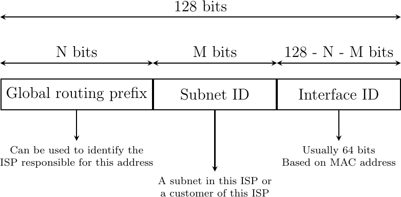
IPv6 supports unicast, multicast and anycast addresses. An IPv6 unicast address is used to identify one datalink-layer interface on a host. If a host has several datalink layer interfaces (e.g. an Ethernet interface and a WiFi interface), then it needs several IPv6 addresses. In general, an IPv6 unicast address is structured as shown in Fig. 113.
Fig. 113 Structure of IPv6 unicast addresses
The IETF has reserved some IPv6 addresses for a special usage. The two most important ones are :
0:0:0:0:0:0:0:1(::1in compact form) is the IPv6 loopback address. This is the address of a logical interface that is always up and running on IPv6 enabled hosts.
0:0:0:0:0:0:0:0(::in compact form) is the unspecified IPv6 address. This is the IPv6 address that a host can use as source address when trying to acquire an official address.
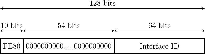
The last type of unicast IPv6 addresses are the Link Local Unicast addresses shown in Fig. 114. These addresses are part of the fe80::/10 address block and are defined in RFC 4291. Each host can compute its own link local address by concatenating the fe80::/64 prefix with the 64 bits identifier of its interface. Link local addresses can be used when hosts that are attached to the same link (or local area network) need to exchange packets. They are used notably for address discovery and auto-configuration purposes. Their usage is restricted to each link and a router cannot forward a packet whose source or destination address is a link local address. Link local addresses have also been defined for IPv4 RFC 3927. However, the IPv4 link local addresses are only used when a host cannot obtain a regular IPv4 address, e.g. on an isolated LAN.
Fig. 114 IPv6 link local address structure
Note
All IPv6 hosts have several addresses
An important consequence of the IPv6 unicast addressing architecture and the utilization of link-local addresses is that each IPv6 host has several IPv6 addresses. This implies that all IPv6 stacks must be able to handle multiple IPv6 addresses.
The addresses described above are unicast addresses. These addresses are used to identify (interfaces on) hosts and routers. They can appear as source and destination addresses in the IPv6 packets. When a host sends a packet towards a unicast address, this packet is delivered by the network to its final destination. There are situations, such as when delivering video or television signal to a large number of receivers, where it is useful to have a network that can efficiently deliver the same packet to a large number of receivers. This is the multicast service. A multicast service can be provided in a LAN. In this case, a multicast address identifies a set of receivers and each frame sent towards this address is delivered to all receivers in the group. Multicast can also be used in a network containing routers and hosts. In this case, a multicast address identifies also a group of receivers and the network delivers efficiently each multicast packet to all members of the group. Consider for example the network shown in Fig. 115.
Fig. 115 A simple network with hosts and routers
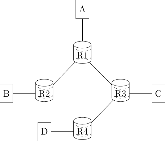
Assume that B and D are part of a multicast group. If A sends a multicast packet towards this group, then R1 will replicate the packet to forward it to R2 and R3. R2 would forward the packet towards B. R3 would forward the packet towards R4 that would deliver it to D.
Finally, RFC 4291 defines the structure of the IPv6 multicast addresses [8]. This structure is depicted in Fig. 116.
Fig. 116 IPv6 multicast address structure
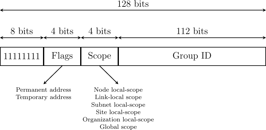
The low order 112 bits of an IPv6 multicast address are the group’s identifier. The high order bits are used as a marker to distinguish multicast addresses from unicast addresses. Notably, the 4-bit Flags field indicates whether the address is temporary or permanent. Finally, the Scope field indicates the boundaries of the forwarding of packets destined to a particular address. A link-local scope indicates that a router should not forward a packet destined to such a multicast address. An organization local-scope indicates that a packet sent to such a multicast destination address should not leave the organization. Finally the global scope is intended for multicast groups spanning the global Internet.
Among these addresses, some are well known. For example, all hosts automatically belong to the ff02::1 multicast group while all routers automatically belong to the ff02::2 multicast group. A detailed discussion of IPv6 multicast is outside the scope of this chapter.
IPv6 packet#
The IPv6 packet format was heavily inspired by the packet format proposed for the SIPP protocol in RFC 1710. The standard IPv6 header defined in RFC 2460 occupies 40 bytes and contains 8 different fields, as shown in Fig. 117.

Apart from the source and destination addresses, the IPv6 header contains the following fields :
Version : a 4 bits field set to 6 and intended to allow IP to evolve in the future if needed
Traffic class : this 8 bits field indicates the type of service expected by this packet and contains the
CEandECTflags that are used by Explicit Congestion NotificationFlow Label : this field was initially intended to be used to tag packets belonging to the same flow. A recent document, RFC 6437 describes some possible usages of this field, but it is too early to tell whether it will be really used.
Payload Length : this is the size of the packet payload in bytes. As the length is encoded as a 16 bits field, an IPv6 packet can contain up to 65535 bytes of payload.
Next Header : this 8-bit field indicates the type [9] of header that follows the IPv6 header. It can be a transport layer header (e.g. 6 for TCP or 17 for UDP) or an IPv6 option.
Hop Limit : this 8-bit field indicates the number of routers that can forward the packet. It is decremented by one by each router and prevents packets from looping forever inside the network.
It is interesting to note that there is no checksum inside the IPv6 header. This is mainly because all datalink layers and transport protocols include a checksum or a CRC to protect their frames/segments against transmission errors. Adding a checksum in the IPv6 header would have forced each router to recompute the checksum of all packets, with limited benefit in detecting errors. In practice, an IP checksum allows for catching errors that occur inside routers (e.g. due to memory corruption) before the packet reaches its destination. However, this benefit was found to be too small given the reliability of current memories and the cost of computing the checksum on each router [10].
When a host receives an IPv6 packet, it needs to determine which transport protocol (UDP, TCP, SCTP, …) needs to handle the payload of the packet. This is the first role of the Next header field. The IANA which manages the allocation of Internet resources and protocol parameters, maintains an official list of transport protocols [9]. The following protocol numbers are reserved :
TCPuses Next Header number6
UDPuses Next Header number17
SCTPuses Next Header number132
For example, an IPv6 packet that contains an TCP segment would appear as shown in Fig. 118.

Fig. 118 An IPv6 packet containing an TCP segment#
However, the Next header has broader usages than simply indicating the transport protocol which is responsible for the packet payload. An IPv6 packet can contain a chain of headers and the last one indicates the transport protocol that is responsible for the packet payload. Supporting a chain of headers is a clever design from an extensibility viewpoint. As we will see, this chain of headers has several usages.
RFC 2460 defines several types of IPv6 extension headers that could be added to an IPv6 packet :
Hop-by-Hop Options header. This option is processed by routers and hosts.
Destination Options header. This option is processed only by hosts.
Routing header. This option is processed by some nodes.
Fragment header. This option is processed only by hosts.
Authentication header. This option is processed only by hosts.
Encapsulating Security Payload. This option is processed only by hosts.
The last two headers are used to add security above IPv6 and implement IPSec. They are described in RFC 2402 and RFC 2406 and are outside the scope of this document.
The Hop-by-Hop Options header was designed to make IPv6 easily extensible. In theory, this option could be used to define new fields that were not foreseen when IPv6 was designed. It is intended to be processed by both routers and hosts. Deploying an extension to a network protocol can be difficult in practice since some nodes already support the extensions while others still use the old version and do not understand the extension. To deal with this issue, the IPv6 designers opted for a Type-Length-Value encoding of these IPv6 options. The Hop-by-Hop Options header is encoded as show in Fig. 119.

Fig. 119 The IPv6 Hop-by-Hop Options header#
In this optional header, the Next Header field is used to support the chain of headers. It indicates the type of the next header in the chain. IPv6 headers have different lengths. The Hdr Ext Len field indicates the total length of the option header in bytes. The Opt. Type field indicates the type of option. These types are encoded such that their high order bits specify how the header needs to be handled by nodes that do not recognize it. The following values are defined for the two high order bits :
00: if a node does not recognize this header, it can be safely skipped and the processing continues with the subsequent header
01: if a node does not recognize this header, the packet must be discarded
10(resp.11) : if a node does not recognize this header, it must return a control packet (ICMP, see later) back to the source (resp. except if the destination was a multicast address)
This encoding allows the designers of protocol extensions to specify whether the option must be supported by all nodes on a path or not. Still, deploying such an extension can be difficult in practice.
Two hop-by-hop options have been defined. RFC 2675 specifies the jumbogram that enables IPv6 to support packets containing a payload larger than 65535 bytes. These jumbo packets have their payload length set to 0 and the jumbogram option contains the packet length as a 32 bits field. Such packets can only be sent from a source to a destination if all the routers on the path support this option. However, as of this writing it does not seem that the jumbogram option has been implemented. The router alert option defined in RFC 2711 is the second example of a hop-by-hop option. The packets that contain this option should be processed in a special way by intermediate routers. This option is used for IP packets that carry Resource Reservation Protocol (RSVP) messages, but this is outside the scope of this book.
The Destinations Option header uses the same format as the Hop-by-Hop Options header. It has some usages, e.g. to support mobile nodes RFC 6275, but these are outside the scope of this document.
The Fragment Options header is more important. An important problem in the network layer is the ability to handle heterogeneous datalink layers. Most datalink layer technologies can only transmit and receive frames that are shorter than a given maximum frame size. Unfortunately, all datalink layer technologies use different maximum frames sizes.
Each datalink layer has its own characteristics and as indicated earlier, each datalink layer is characterized by a maximum frame size. From IP’s point of view, a datalink layer interface is characterized by its Maximum Transmission Unit (MTU). The MTU of an interface is the largest packet (including header) that it can send. The table below provides some common MTU sizes.
Datalink layer |
MTU |
Ethernet |
1500 bytes |
WiFi |
2272 bytes |
ATM (AAL5) |
9180 bytes |
802.15.4 |
102 or 81 bytes |
Token Ring |
4464 bytes |
FDDI |
4352 bytes |
Although IPv6 can send 64 KBytes long packets, few datalink layer technologies that are used today are able to send a 64 KBytes packet inside a frame. Furthermore, as illustrated in Fig. 120, another problem is that a host may send a packet that would be too large for one of the datalink layers used by the intermediate routers.
Fig. 120 The need for fragmentation and reassembly
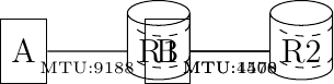
To solve these problems, IPv6 includes a packet fragmentation and reassembly mechanism. In IPv4, fragmentation was performed by both the hosts and the intermediate routers. However, experience with IPv4 has shown that fragmenting packets in routers was costly [KM1995]. For this reason, the developers of IPv6 have decided that routers would not fragment packets anymore. In IPv6, fragmentation is only performed by the source host. If a source has to send a packet which is larger than the MTU of the outgoing interface, the packet needs to be fragmented before being transmitted. In IPv6, each packet fragment is an IPv6 packet that includes the Fragmentation header shown in Fig. 121. This header is included by the source in each packet fragment. The receiver uses them to reassemble the received fragments.

Fig. 121 IPv6 fragmentation header#
If a router receives a packet that is too long to be forwarded, the packet is dropped and the router returns an ICMPv6 message to inform the sender of the problem. The sender can then either fragment the packet or perform Path MTU discovery. In IPv6, packet fragmentation is performed only by the source by using IPv6 options.
In IPv6, fragmentation is performed exclusively by the source host and relies on the fragmentation header. This 64 bits header is composed of six fields :
a Next Header field that indicates the type of the header that follows the fragmentation header
two Reserved fields set to 0.
the Fragment Offset is a 13-bit unsigned integer that contains the offset, in 8 bytes units, of the data following this header, relative to the start of the original packet.
the More flag, which is set to 0 in the last fragment of a packet and to 1 in all other fragments.
the 32-bit Identification field indicates to which original packet a fragment belongs. When a host sends fragmented packets, it should ensure that it does not reuse the same identification field for packets sent to the same destination during a period of MSL seconds. This is easier with the 32 bits identification used in the IPv6 fragmentation header, than with the 16 bits identification field of the IPv4 header.
Some IPv6 implementations send the fragments of a packet in increasing fragment offset order, starting from the first fragment. Others send the fragments in reverse order, starting from the last fragment. The latter solution can be advantageous for the host that needs to reassemble the fragments, as it can easily allocate the buffer required to reassemble all fragments of the packet upon reception of the last fragment. When a host receives the first fragment of an IPv6 packet, it cannot know a priori the length of the entire IPv6 packet.
Fig. 122 provides an example of a fragmented IPv6 packet containing a UDP segment. The Next Header type reserved for the IPv6 fragmentation option is 44.
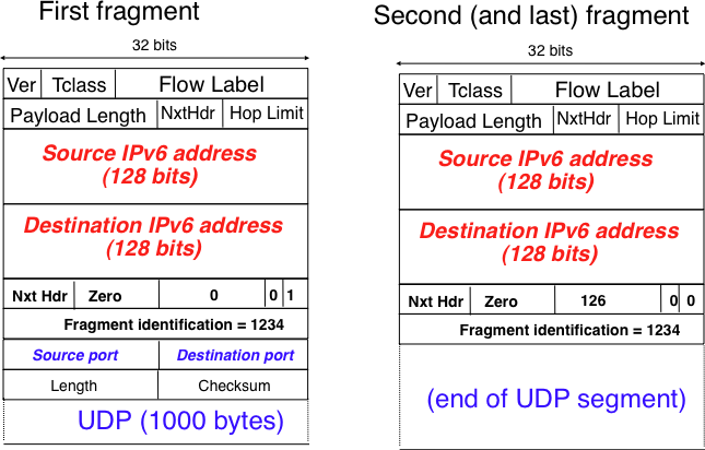
Fig. 122 IPv6 fragmentation example#
The following pseudo-code details the IPv6 fragmentation, assuming that the packet does not contain options.
# mtu : maximum size of the packet (including header) of outgoing link
# In Scapy-like notation (see https://github.com/secdev/scapy)
if p.len < mtu:
    send(p)
else:
    # packet is too large
    # 40 refers to the size of the IPv6 header
    maxpayload = 8 * int((mtu - 40) / 8)  # must be n times 8 bytes
    # packet must be fragmented
    payload = p[IPv6].payload
    pos = 0
    id = globalCounter
    globalCounter += 1
    while len(payload) > 0:
        if len(payload) > maxpayload:
            toSend = IPv6(dst=p.dst, src=p.src, plen=mtu,
                          hlim=p.hlim, nh=44)/IPv6ExtHdrFrament(
                              id=id, offset=p.offset + (pos/8), m=True,
                              nh=p.nh)/payload[0:maxpayload]
            pos = pos + maxpayload
            payload = payload[maxpayload+1:]
        else:
            # The last fragment
            toSend = IPv6(dst=p.dst, src=p.src, plen=len(payload),
                          hlim=p.hlim, nh=44)/IPv6ExtHdrFrament(
                              id=id, offset=p.offset + (pos/8), m=False,
                              nh=p.nh)/payload
            payload = []

        forward(toSend)
In the above pseudocode, we maintain a single 32 bits counter that is incremented for each packet that needs to be fragmented. Other implementations to compute the packet identification are possible. RFC 2460 only requires that two fragmented packets that are sent within the MSL between the same pair of hosts have different identifications.
The fragments of an IPv6 packet may arrive at the destination in any order, as each fragment is forwarded independently in the network and may follow different paths. Furthermore, some fragments may be lost and never reach the destination.
The reassembly algorithm used by the destination host is roughly as follows. First, the destination can verify whether a received IPv6 packet is a fragment or not by checking whether it contains a fragment header. If so, all fragments with the some identification must be reassembled together. The reassembly algorithm relies on the Identification field of the received fragments to associate a fragment with the corresponding packet being reassembled. Furthermore, the Fragment Offset field indicates the position of the fragment payload in the original non-fragmented packet. Finally, the packet with the M flag reset allows the destination to determine the total length of the original non-fragmented packet.
Note that the reassembly algorithm must deal with the unreliability of the IP network. This implies that a fragment may be duplicated or a fragment may never reach the destination. The destination can easily detect fragment duplication thanks to the Fragment Offset. To deal with fragment losses, the reassembly algorithm must bind the time during which the fragments of a packet are stored in its buffer while the packet is being reassembled. This can be implemented by starting a timer when the first fragment of a packet is received. If the packet has not been reassembled upon expiration of the timer, all fragments are discarded and the packet is considered to be lost.
Note
Header compression on low bandwidth links
Given the size of the IPv6 header, it can cause huge overhead on low bandwidth links, especially when small packets are exchanged such as for Voice over IP applications. In such environments, several techniques can be used to reduce the overhead. A first solution is to use data compression in the datalink layer to compress all the information exchanged [Thomborson1992]. These techniques are similar to the data compression algorithms used in tools such as compress(1) or gzip(1) RFC 1951. They compress streams of bits without taking advantage of the fact that these streams contain IP packets with a known structure. A second solution is to compress the IP and TCP header. These header compression techniques, such as the one defined in RFC 5795 take advantage of the redundancy found in successive packets from the same flow to significantly reduce the size of the protocol headers. Another solution is to define a compressed encoding of the IPv6 header that matches the capabilities of the underlying datalink layer RFC 4944.
The last type of IPv6 header extension is the Routing header. The type 0 routing header defined in RFC 2460 is an example of an IPv6 option that must be processed by some routers. This option is encoded as shown in Fig. 123.

The type 0 routing option was intended to allow a host to indicate a loose source route that should be followed by a packet by specifying the addresses of some of the routers that must forward this packet. Unfortunately, further work with this routing header, including an entertaining demonstration with scapy [BE2007] , revealed severe security problems with this routing header. For this reason, loose source routing with the type 0 routing header has been removed from the IPv6 specification RFC 5095.
ICMP version 6#
It is sometimes necessary for intermediate routers or the destination host to inform the sender of the packet of a problem that occurred while processing a packet. In the TCP/IP protocol suite, this reporting is done by the Internet Control Message Protocol (ICMP). ICMPv6 is defined in RFC 4443. It is used both to report problems that occurred while processing an IPv6 packet, but also to distribute addresses.
ICMPv6 messages are carried inside IPv6 packets (the Next Header field for ICMPv6 is 58). Each ICMP message contains a 32 bits header with an 8 bits type field, a code field and a 16 bits checksum computed over the entire ICMPv6 message. The message body contains a copy of the IPv6 packet in error. The ICMPv6 header is shown in Fig. 124.

Fig. 124 ICMP version 6 packet format#
ICMPv6 specifies two classes of messages : error messages that indicate a problem in handling a packet and informational messages. Four types of error messages are defined in RFC 4443 :
1Destination Unreachable. Such an ICMPv6 message is sent when the destination address of a packet is unreachable. The code field of the ICMP header contains additional information about the type of unreachability. The following codes are specified in RFC 4443
0: No route to destination. This indicates that the router that sent the ICMPv6 message did not have a route towards the packet’s destination
1: Communication with destination administratively prohibited. This indicates that a firewall has refused to forward the packet towards its final destination.
2: Beyond scope of source address. This message can be sent if the source is using link-local addresses to reach a global unicast address outside its subnet.
3: Address unreachable. This message indicates that the packet reached the subnet of the destination, but the host that owns this destination address cannot be reached.
4: Port unreachable. This message indicates that the IPv6 packet was received by the destination, but there was no application listening to the specified port.
2: Packet Too Big. The router that was to send the ICMPv6 message received an IPv6 packet that is larger than the MTU of the outgoing link. The ICMPv6 message contains the MTU of this link in bytes. This allows the sending host to implement Path MTU discovery RFC 1981
3: Time Exceeded. This error message can be sent either by a router or by a host. A router would set code to 0 to report the reception of a packet whose Hop Limit reached 0. A host would set code to 1 to report that it was unable to reassemble received IPv6 fragments.
4: Parameter Problem. This ICMPv6 message is used to report either the reception of an IPv6 packet with an erroneous header field (code 0) or an unknown Next Header or IP option (codes 1 and 2). In this case, the message body contains the erroneous IPv6 packet and the first 32 bits of the message body contain a pointer to the error.
The Destination Unreachable ICMP error message is returned when a packet cannot be forwarded to its final destination. The first four ICMPv6 error messages (type 1, codes 0-3) are generated by routers while hosts may return code 4 when there is no application bound to the corresponding port number.
The Packet Too Big ICMP messages enable the source host to discover the MTU size that it can safely use to reach a given destination. To understand its operation, consider the (academic) scenario shown in Fig. 125. In this figure, the labels on each link represent the maximum packet size supported by this link.
Fig. 125 Example for IPv6 MTU discovery
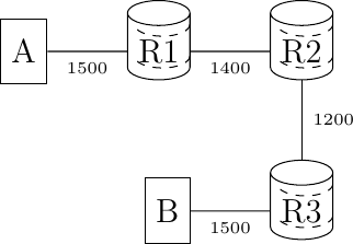
If A sends a 1500 bytes packet, R1 will return an ICMPv6 error message indicating a maximum packet length of 1400 bytes. A would then fragment the packet before retransmitting it. The small fragment would go through, but the large fragment will be refused by R2 that would return an ICMPv6 error message. A can fragment again the packet and send it to the final destination as two fragments.
In practice, an IPv6 implementation does not store the transmitted packets to be able to retransmit them if needed. However, since TCP (and SCTP) buffer the segments that they transmit, a similar approach can be used in transport protocols to detect the largest MTU on a path towards a given destination. This technique is called PathMTU Discovery RFC 1981.
When a TCP segment is transported in an IP packet that is fragmented in the network, the loss of a single fragment forces TCP to retransmit the entire segment (and thus all the fragments). If TCP was able to send only packets that do not require fragmentation in the network, it could retransmit only the information that was lost in the network. In addition, IP reassembly causes several challenges at high speed as discussed in RFC 4963. Using IP fragmentation to allow UDP applications to exchange large messages raises several security issues [KPS2003].
ICMPv6 is used by TCP implementations to discover the largest MTU size that is allowed to reach a destination host without causing network fragmentation. A TCP implementation parses the Packets Too Big ICMP messages that it receives. These ICMP messages contain the MTU of the router’s outgoing link in their Data field. Upon reception of such an ICMP message, the source TCP implementation adjusts its Maximum Segment Size (MSS) so that the packets containing the segments that it sends can be forwarded by this router without requiring fragmentation.
Two types of informational ICMPv6 messages are defined in RFC 4443 : echo request and echo reply, which are used to test the reachability of a destination by using ping6(8). Each host is supposed to reply with an ICMP Echo reply message when it receives an ICMP Echo request message. A sample usage of ping6(8) is shown below.
#ping6 www.ietf.org
PING6(56=40+8+8 bytes) 2001:6a8:3080:2:3403:bbf4:edae:afc3 --> 2001:1890:123a::1:1e
16 bytes from 2001:1890:123a::1:1e, icmp_seq=0 hlim=49 time=156.905 ms
16 bytes from 2001:1890:123a::1:1e, icmp_seq=1 hlim=49 time=155.618 ms
16 bytes from 2001:1890:123a::1:1e, icmp_seq=2 hlim=49 time=155.808 ms
16 bytes from 2001:1890:123a::1:1e, icmp_seq=3 hlim=49 time=155.325 ms
16 bytes from 2001:1890:123a::1:1e, icmp_seq=4 hlim=49 time=155.493 ms
16 bytes from 2001:1890:123a::1:1e, icmp_seq=5 hlim=49 time=155.801 ms
16 bytes from 2001:1890:123a::1:1e, icmp_seq=6 hlim=49 time=155.660 ms
16 bytes from 2001:1890:123a::1:1e, icmp_seq=7 hlim=49 time=155.869 ms
^C
--- www.ietf.org ping6 statistics ---
8 packets transmitted, 8 packets received, 0.0% packet loss
round-trip min/avg/max/std-dev = 155.325/155.810/156.905/0.447 ms
Another very useful debugging tool is traceroute6(8). The traceroute man page describes this tool as “print the route packets take to network host”. traceroute uses the Time exceeded ICMP messages to discover the intermediate routers on the path towards a destination. The principle behind traceroute is very simple. When a router receives an IP packet whose Hop Limit is set to 1 it is forced to return to the sending host a Time exceeded ICMP message containing the header and the first bytes of the discarded packet. To discover all routers on a network path, a simple solution is to first send a packet whose Hop Limit is set to 1, then a packet whose Hop Limit is set to 2, etc. A sample traceroute6 output is shown below.
#traceroute6 www.ietf.org
traceroute6 to www.ietf.org (2001:1890:1112:1::20) from 2001:6a8:3080:2:217:f2ff:fed6:65c0, 30 hops max, 12 byte packets
 1  2001:6a8:3080:2::1  13.821 ms  0.301 ms  0.324 ms
 2  2001:6a8:3000:8000::1  0.651 ms  0.51 ms  0.495 ms
 3  10ge.cr2.bruvil.belnet.net  3.402 ms  3.34 ms  3.33 ms
 4  10ge.cr2.brueve.belnet.net  3.668 ms 10ge.cr2.brueve.belnet.net  3.988 ms 10ge.cr2.brueve.belnet.net  3.699 ms
 5  belnet.rt1.ams.nl.geant2.net  10.598 ms  7.214 ms  10.082 ms
 6  so-7-0-0.rt2.cop.dk.geant2.net  20.19 ms  20.002 ms  20.064 ms
 7  kbn-ipv6-b1.ipv6.telia.net  21.078 ms  20.868 ms  20.864 ms
 8  s-ipv6-b1-link.ipv6.telia.net  31.312 ms  31.113 ms  31.411 ms
 9  s-ipv6-b1-link.ipv6.telia.net  61.986 ms  61.988 ms  61.994 ms
 10  2001:1890:61:8909::1  121.716 ms  121.779 ms  121.177 ms
 11  2001:1890:61:9117::2  203.709 ms  203.305 ms  203.07 ms
 12  mail.ietf.org  204.172 ms  203.755 ms  203.748 ms
Note
Rate limitation of ICMP messages
High-end hardware based routers use special purpose chips on their interfaces to forward IPv6 packets at line rate. These chips are optimized to process correct IP packets. They are not able to create ICMP messages at line rate. When such a chip receives an IP packet that triggers an ICMP message, it interrupts the main CPU of the router and the software running on this CPU processes the packet. This CPU is much slower than the hardware acceleration found on the interfaces [Gill2004]. It would be overloaded if it had to process IP packets at line rate and generate one ICMP message for each received packet. To protect this CPU, high-end routers limit the rate at which the hardware can interrupt the main CPU and thus the rate at which ICMP messages can be generated. This implies that not all erroneous IP packets cause the transmission of an ICMP message. The risk of overloading the main CPU of the router is also the reason why using hop-by-hop IPv6 options, including the router alert option is discouraged [#falert]_.
Footnotes