Networked applications#
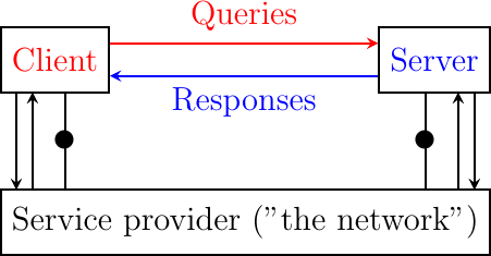
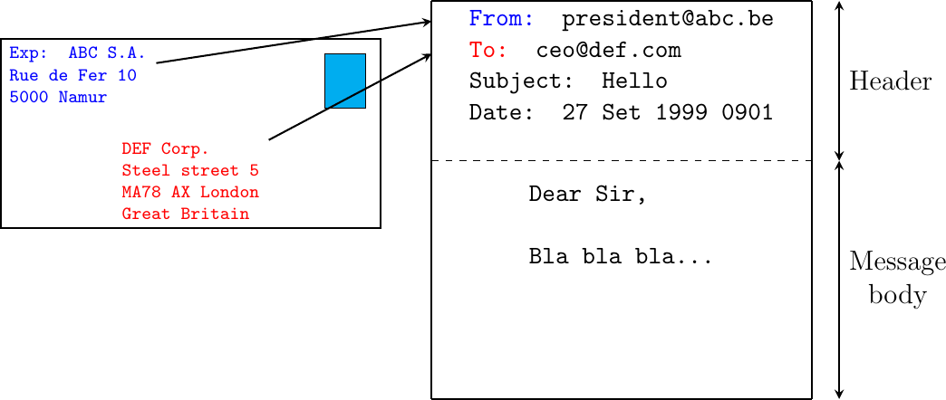
There are two important models used to organize a networked application. The first and oldest model is the client-server model. In this model, a server provides services to clients that exchange information with it. This model is highly asymmetrical: clients send requests and servers perform actions and return responses. It is illustrated in the Fig. 20.
Fig. 20 The client-server model
The client-server model was the first model to be used to develop networked applications. This model comes naturally from the mainframes and minicomputers that were the only networked computers used until the 1980s. A minicomputer is a multi-user system that is used by tens or more users at the same time. Each user interacts with the minicomputer by using a terminal. Such a terminal was mainly a screen, a keyboard and a cable directly connected to the minicomputer.
There are various types of servers as well as various types of clients. A web server provides information in response to the query sent by its clients. A print server prints documents sent as queries by the client. An email server forwards towards their recipient the email messages sent as queries while a music server delivers the music requested by the client. From the viewpoint of the application developer, the client and the server applications directly exchange messages (the horizontal arrows labeled Queries and Responses in the above figure), but in practice these messages are exchanged thanks to the underlying layers (the vertical arrows in the above figure). In this chapter, we focus on these horizontal exchanges of messages.
Networked applications do not exchange random messages. In order to ensure that the server is able to understand the queries sent by a client, and also that the client is able to understand the responses sent by the server, they must both agree on a set of syntactical and semantic rules. These rules define the format of the messages exchanged as well as their ordering. This set of rules is called an application-level protocol.
An application-level protocol is similar to a structured conversation between humans. Assume that Alice wants to know the current time but does not have a watch. If Bob passes close by, the following conversation could take place :
Alice : Hello
Bob : Hello
Alice : What time is it ?
Bob : 11:55
Alice : Thank you
Bob : You’re welcome
Such a conversation succeeds if both Alice and Bob speak the same language. If Alice meets Tchang who only speaks Chinese, she won’t be able to ask him the current time. A conversation between humans can be more complex. For example, assume that Bob is a security guard whose duty is to only allow trusted secret agents to enter a meeting room. If all agents know a secret password, the conversation between Bob and Trudy could be as follows :
Bob : What is the secret password ?
Trudy : 1234
Bob : This is the correct password, you’re welcome
If Alice wants to enter the meeting room but does not know the password, her conversation could be as follows :
Bob : What is the secret password ?
Alice : 3.1415
Bob : This is not the correct password.
Human conversations can be very formal, e.g. when soldiers communicate with their hierarchy, or informal such as when friends discuss. Computers that communicate are more akin to soldiers and require well-defined rules to ensure a successful exchange of information. There are two types of rules that define how information can be exchanged between computers :
Syntactical rules that precisely define the format of the messages that are exchanged. As computers only process bits, the syntactical rules specify how information is encoded as bit strings.
Organization of the information flow. For many applications, the flow of information must be structured and there are precedence relationships between the different types of information. In the time example above, Alice must greet Bob before asking for the current time. Alice would not ask for the current time first and greet Bob afterwards. Such precedence relationships exist in networked applications as well. For example, a server must receive a username and a valid password before accepting more complex commands from its clients.
Let us first discuss the syntactical rules. We will later explain how the information flow can be organized by analyzing real networked applications.
Application-layer protocols exchange two types of messages. Some protocols such as those used to support electronic mail exchange messages expressed as strings or lines of characters. As the transport layer allows hosts to exchange bytes, they need to agree on a common representation of the characters. The first and simplest method to encode characters is to use the ASCII table. RFC 20 provides the ASCII table that is used by many protocols on the Internet. For example, the table defines the following binary representations :
A : 1000011b
0 : 0110000b
z : 1111010b
@ : 1000000b
space : 0100000b
In addition, the ASCII table also defines several non-printable or control characters. These characters were designed to allow an application to control a printer or a terminal. These control characters include CR and LF, that are used to terminate a line, and the Bell character which causes the terminal to emit a sound.
carriage return (CR) : 0001101b
line feed (LF) : 0001010b
Bell: 0000111b
The ASCII characters are encoded as a seven bits field, but transmitted as an eight-bits byte whose high order bit is usually set to 0. Bytes are always transmitted starting from the high order or most significant bit.
Most applications exchange strings that are composed of fixed or variable numbers of characters. A common solution to define the character strings that are acceptable is to define them as a grammar using a Backus-Naur Form (BNF) such as the Augmented BNF defined in RFC 5234. A BNF is a set of production rules that generate all valid character strings. For example, consider a networked application that uses two commands, where the user can supply a username and a password. The BNF for this application could be defined as shown in Fig. 21.

Fig. 21 A simple BNF specification#
The example above defines several terminals and two commands : usercommand and passwordcommand. The ALPHA terminal contains all letters in upper and lower case. In the ALPHA rule, %x41 corresponds to ASCII character code 41 in hexadecimal, i.e. capital A. The CR and LF terminals correspond to the carriage return and linefeed control characters. The CRLF rule concatenates these two terminals to match the standard end of line termination. The DIGIT terminal contains all digits. The SP terminal corresponds to the white space characters. The usercommand is composed of two strings separated by white space. In the ABNF rules that define the messages used by Internet applications, the commands are case-insensitive. The rule “user” corresponds to all possible cases of the letters that compose the word between brackets, e.g. user, uSeR, USER, usER, … A username contains at least one letter and up to 8 letters. User names are case-sensitive as they are not defined as a string between brackets. The password rule indicates that a password starts with a letter and can contain any number of letters or digits. The white space and the control characters cannot appear in a password defined by the above rule.
Besides character strings, some applications also need to exchange 16 bits and 32 bits fields such as integers. A naive solution would have been to send the 16- or 32-bits field as it is encoded in the host’s memory. Unfortunately, there are different methods to store 16- or 32-bits fields in memory. Some CPUs store the most significant byte of a 16-bits field in the first address of the field while others store the least significant byte at this location. When networked applications running on different CPUs exchange 16 bits fields, there are two possibilities to transfer them over the transport service :
send the most significant byte followed by the least significant byte
send the least significant byte followed by the most significant byte
The first possibility was named big-endian in a note written by Cohen [Cohen1980] while the second was named little-endian. Vendors of CPUs that used big-endian in memory insisted on using big-endian encoding in networked applications while vendors of CPUs that used little-endian recommended the opposite. Several studies were written on the relative merits of each type of encoding, but the discussion became almost a religious issue [Cohen1980]. Eventually, the Internet chose the big-endian encoding, i.e. multi-byte fields are always transmitted by sending the most significant byte first, RFC 791 refers to this encoding as the network-byte order. Most libraries [9] used to write networked applications contain functions to convert multi-byte fields from memory to the network byte order and the reverse.
Besides 16 and 32 bit words, some applications need to exchange data structures containing bit fields of various lengths. For example, a message may be composed of a 16 bits field followed by eight, one bit flags, a 24 bits field and two 8 bits bytes. Internet protocol specifications will define such a message by using a representation such as Fig. 22. In this representation, each line corresponds to 32 bits and the vertical lines are used to delineate fields. The numbers above the lines indicate the bit positions in the 32-bits word, with the high order bit at position 0.

Fig. 22 Message format#
The message mentioned above will be transmitted starting from the upper 32-bits word in network byte order. The first field is encoded in 16 bits. It is followed by eight one bit flags (A-H), a 24 bits field whose high order byte is shown in the first line and the two low order bytes appear in the second line followed by two one byte fields. This ASCII representation is frequently used when defining binary protocols. We will use it for all the binary protocols that are discussed in this book.
The peer-to-peer model emerged during the last ten years as another possible architecture for networked applications. In the traditional client-server model, hosts act either as servers or as clients and a server serves a large number of clients. In the peer-to-peer model, all hosts act as both servers and clients and they play both roles. The peer-to-peer model has been used to develop various networked applications, ranging from Internet telephony to file sharing or Internet-wide filesystems. A detailed description of peer-to-peer applications may be found in [BYL2008]. Surveys of peer-to-peer protocols and applications may be found in [AS2004] and [LCP2005].
Naming and addressing#
The network and the transport layers rely on addresses that are encoded as fixed-size bit strings. A network layer address uniquely identifies a host. Several transport layer entities can use the service of the same network layer. For example, a reliable transport protocol and a connectionless transport protocol can coexist on the same host. In this case, the network layer multiplexes the segments produced by these two protocols. This multiplexing is usually achieved by placing in the network packet header a field that indicates which transport protocol should process the segment. Given that there are few different transport protocols, this field does not need to be long. The port numbers play a similar role in the transport layer since they enable it to multiplex data from several application processes.
While addresses are natural for the network and transport layer entities, humans prefer to use names when interacting with network services. Names can be encoded as a character string, and a mapping service allows applications to map a name into the corresponding address. Using names is friendlier for humans, but it also provides a level of indirection which is very useful in many situations.
In the early days of the Internet, only a few hosts (mainly minicomputers) were connected to the network. The most popular applications were remote login and file transfer. By 1983, there were already five hundred hosts attached to the Internet [Zakon]. Each of these hosts was identified by a unique address. Forcing human users to remember the addresses of the hosts that they wanted to use was not user-friendly. Humans prefer to remember names and use them when needed. Using names as aliases for addresses is a common technique in Computer Science. It simplifies the development of applications and allows the developer to ignore the low-level details. For example, by using a programming language instead of writing machine code, a developer can write software without knowing whether the variables that it uses are stored in memory or inside registers.
Because names are at a higher level than addresses, they allow (both in the example of programming above and on the Internet) to treat addresses as mere technical identifiers, which can change at will. Only the names are stable.
The first solution that allowed applications to use names was the hosts.txt file. This file is similar to the symbol table found in compiled code. It contains the mapping between the name of each Internet host and its associated address [1]. It was maintained by the SRI International Network Information Center (NIC). When a new host was connected to the network, the system administrator had to register its name and address at the NIC. The NIC updated the hosts.txt file on its server. All Internet hosts regularly retrieved the updated hosts.txt file from the SRI server. This file was stored at a well-known location on each Internet host (see RFC 952) and networked applications could use it to find the address corresponding to a name.
A hosts.txt file can be used when there are up to a few hundred hosts on the network. However, it is clearly not suitable for a network containing thousands or millions of hosts. A key issue in a large network is to define a suitable naming scheme. The ARPANet initially used a flat naming space, i.e. each host was assigned a unique name. To limit collisions between names, these names usually contained the name of the institution and a suffix to identify the host inside the institution (a kind of poor man’s hierarchical naming scheme). On the ARPANet, few institutions had several hosts connected to the network.
However, the limitations of a flat naming scheme became clear before the end of the ARPANet, and RFC 819 proposed a hierarchical naming scheme. While RFC 819 discussed the possibility of organizing the names as a directed graph, the Internet opted for a tree structure capable of containing all names. In this tree, the top-level domains are those that are directly attached to the root. The first top-level domain was .arpa [2]. This top-level name was initially added as a suffix to the names of the hosts attached to the ARPANet and listed in the hosts.txt file. In 1984, the .gov, .edu, .com, .mil, and .org generic top-level domain names were added. RFC 1032 proposed the utilization of the two-letter ISO-3166 country codes as top-level domain names. Since ISO-3166 defines a two-letter code for each country recognized by the United Nations, this allowed all countries to automatically have a top-level domain. These domains include .be for Belgium, .fr for France, .us for the USA, .ie for Ireland, or .tv for Tuvalu, a group of small islands in the Pacific, or .tm for Turkmenistan. The set of top-level domain names is managed by the Internet Corporation for Assigned Names and Numbers (ICANN). ICANN adds generic top-level domains that are not related to a country, and the .cat top-level domain has been registered for the Catalan language. There are ongoing discussions within ICANN to increase the number of top-level domains.
Each top-level domain is managed by an organization that decides how subdomain names can be registered. Most top-level domain names use a first-come, first-served system and allow anyone to register domain names, but there are some exceptions. For example, .gov is reserved for the US government, .int is reserved for international organizations, and names in the .ca are mainly reserved for companies or users that are present in Canada.
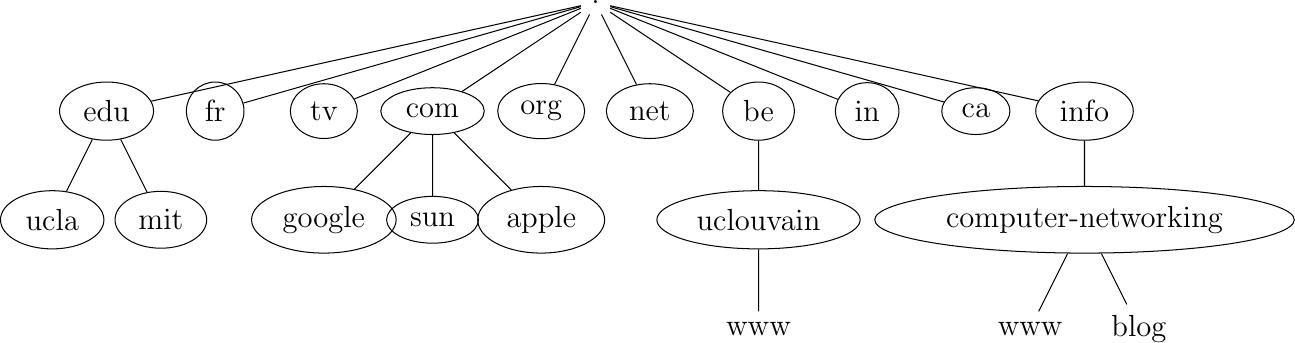
Fig. 23 The tree of domain names
The syntax of the domain names has been defined more precisely in RFC 1035. This document recommends the following BNF for fully qualified domain names (the domain names themselves have a much richer syntax).
domain ::= subdomain | " "
subdomain ::= label | subdomain "." label
label ::= letter [ [ ldh-str ] let-dig ]
ldh-str ::= let-dig-hyp | let-dig-hyp ldh-str
let-dig-hyp ::= let-dig | "-"
let-dig ::= letter | digit
letter ::= any one of the 52 alphabetic characters A through Z in upper case and a through z in lower case
digit ::= any one of the ten digits 0 through 9
This grammar specifies that a host name is an ordered list of labels separated by the dot (.) character. Each label can contain letters, numbers, and the hyphen character (-) [3]. Fully qualified domain names are read from left to right. The first label is a hostname or a domain name followed by the hierarchy of domains and ending with the root implicitly at the right. The top-level domain name must be one of the registered TLDs [4]. For example, in the above figure, www.computer-networking.info corresponds to a host named www inside the computer-networking domain that belongs to the info top-level domain.
Note
Some visually similar characters have different character codes
The Domain Name System was created at a time when the Internet was mainly used in North America. The initial design assumed that all domain names would be composed of letters and digits RFC 1035. As Internet usage grew in other parts of the world, it became important to support non-ASCII characters. For this, extensions have been proposed to the Domain Name System RFC 3490. In a nutshell, the solution that is used to support Internationalized Domain Names works as follows. First, it is possible to use most of the Unicode characters to encode domain names and hostnames, with a few exceptions (for example, the dot character cannot be part of a name since it is used as a separator). Once a domain name has been encoded as a series of Unicode characters, it is then converted into a string that contains the xn-- prefix and a sequence of ASCII characters. More details on these algorithms can be found in RFC 3490 and RFC 3492.
The possibility of using all Unicode characters to create domain names opened a new form of attack called the homograph attack. This attack occurs when two character strings or domain names are visually similar but do not correspond to the same server. A simple example is https://G00GLE.COM and https://GOOGLE.COM. These two URLs are visually close but they correspond to different names (the first one does not point to a valid server [5]). With other Unicode characters, it is possible to construct domain names that are visually equivalent to existing ones. See [Zhe2017] for additional details on this attack.
This hierarchical naming scheme is a key component of the Domain Name System (DNS). The DNS is a distributed database that contains mappings between fully qualified domain names and addresses. The DNS uses the client-server model. The clients are hosts or applications that need to retrieve the mapping for a given name. Each nameserver stores part of the distributed database and answers the queries sent by clients. There is at least one nameserver that is responsible for each domain. In the figure below, domains are represented by circles and there are three hosts inside domain dom (h1, h2, and h3) and three hosts inside domain a.sdom1.dom. As shown in the figure below, a sub-domain may contain both host names and sub-domains.
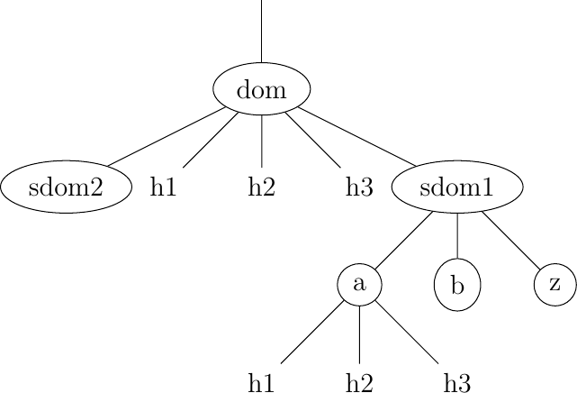
Fig. 24 A simple tree of domain names
A nameserver that is responsible for domain dom can directly answer the following queries :
the address of any host residing directly inside domain dom (e.g. h2.dom in the figure above)
the nameserver(s) that are responsible for any direct sub-domain of domain dom (i.e. sdom1.dom and sdom2.dom in the figure above, but not z.sdom1.dom)
To retrieve the mapping for host h2.dom, a client sends its query to the name server that is responsible for the domain .dom. The name server directly answers the query. To retrieve a mapping for h3.a.sdom1.dom, a DNS client first sends a query to the name server that is responsible for the .dom domain. This nameserver returns the nameserver that is responsible for the sdom1.dom domain. This nameserver can now be contacted to obtain the nameserver that is responsible for the a.sdom1.dom domain. This nameserver can be contacted to retrieve the mapping for the h3.a.sdom1.dom name. Thanks to this structure, it is possible for a DNS client to obtain the mapping of any host inside the .dom domain or any of its subdomains. To ensure that any DNS client will be able to resolve any fully qualified domain name, there are special nameservers that are responsible for the root of the domain name hierarchy. These nameservers are called root nameserver.
Each root nameserver maintains the list [6] of all the nameservers that are responsible for each of the top-level domain names and their addresses [7]. All root nameservers cooperate and provide the same answers. By querying any of the root nameservers, a DNS client can obtain the nameserver that is responsible for any top-level-domain name. From this nameserver, it is possible to resolve any domain name.
To be able to contact the root nameservers, each DNS client must know their addresses. This implies that DNS clients must maintain an up-to-date list of the addresses of the root nameservers. Without this list, it is impossible to contact the root nameservers. Forcing all Internet hosts to maintain the most recent version of this list would be difficult from an operational point of view. To solve this problem, the designers of the DNS introduced a special type of DNS server : the DNS resolvers. A resolver is a server that provides the name resolution service for a set of clients. A network usually contains a few resolvers. Each host in these networks is configured to send all its DNS queries via one of its local resolvers. These queries are called recursive queries as the resolver must recursively send requests through the hierarchy of nameservers to obtain the answer.
DNS resolvers have several advantages over letting each Internet host query directly nameservers. Firstly, regular Internet hosts do not need to maintain the up-to-date list of the addresses of the root servers. Secondly, regular Internet hosts do not need to send queries to nameservers all over the Internet. Furthermore, as a DNS resolver serves a large number of hosts, it can cache the received answers. This allows the resolver to quickly return answers for popular DNS queries and reduces the load on all DNS servers [JSBM2002].
Benefits of names#
In addition to being more human-friendly, using names instead of addresses inside applications has several important benefits. To understand them, let us consider a popular application that provides information stored on servers. This application involves clients and servers. The server provides information upon requests from client processes. A first deployment of this application would be to rely only on addresses. In this case, the server process would be installed on one host, and the clients would connect to this server to retrieve information. Such a deployment has several drawbacks :
if the server process moves to another physical server, all clients must be informed about the new server address.
if there are many concurrent clients, the load of the server will increase without any possibility of adding another server without changing the server addresses used by the clients.
Using names solves these problems and provides additional benefits. If the clients are configured with the name of the server, they will query the name service before contacting the server. The name service will resolve the name into the corresponding address. If a server process needs to move from one physical server to another, it suffices to update the name-to-address mapping on the name service to allow all clients to connect to the new server. The name service also enables the servers to better sustain the load. Assume a very popular server which is accessed by millions of users. This service cannot be provided by a single physical server due to performance limitations. Thanks to the utilization of names, it is possible to scale this service by mapping a given name to a set of addresses. When a client queries the name service for the server’s name, the name service returns one of the addresses in the set. Various strategies can be used to select one particular address inside the set of addresses. A first strategy is to select a random address in the set. A second strategy is to maintain information about the load on the servers and return the address of the less loaded server. Note that the list of server addresses does not need to remain fixed. It is possible to add and remove addresses from the list to cope with load fluctuations. Another strategy is to infer the location of the client from the name request and return the address of the closest server.
Mapping a single name onto a set of addresses allows popular servers to dynamically scale. There are also benefits in mapping multiple names, possibly a large number of them, onto a single address. Consider the case of information servers run by individuals or SMEs. Some of these servers attract only a few clients per day. Using a single physical server for each of these services would be a waste of resources. A better approach is to use a single server for a set of services that are all identified by different names. This enables service providers to support a large number of server processes, identified by different names, onto a single physical server. If one of these server processes becomes very popular, it will be possible to map its name onto a set of addresses to be able to sustain the load. There are some deployments where this mapping is done dynamically in function of the load.
Names provide a lot of flexibility compared to addresses. For the network, they play a similar role as variables in programming languages. No programmer using a high-level programming language would consider using hardcoded values instead of variables. For the same reasons, all networked applications should depend on names and avoid dealing with addresses as much as possible.
The Domain Name System#
The last component of the Domain Name System is the DNS protocol. The original DNS protocol runs above both the datagram and the bytestream services. In practice, the datagram service is used when short queries and responses are exchanged, and the bytestream service is used when longer responses are expected. In this section, we first focus on the utilization of the DNS protocol above the datagram service. We will discuss later other recently proposed protocols to carry DNS information.
DNS messages are composed of five parts that are named sections in RFC :1035. The first three sections are mandatory, and the last two sections are optional. The first section of a DNS message is its Header. It contains information about the message type and the content of the other sections. The second section contains the Question sent to the nameserver or resolver. The third section contains the Answer to the Question. When a client sends a DNS query, the Answer section is empty. The fourth section, named Authority, contains information about the servers that can provide an authoritative answer if required. The last section contains additional information that is supplied by the resolver or nameserver but was not requested in the question.
The header of DNS messages is composed of 12 bytes. The figure below presents its structure.

Fig. 25 The DNS header#
The Transaction ID (transaction identifier) is a 16-bit random value chosen by the client. When a client sends a question to a DNS server, it remembers the question and its identifier. When a server returns an answer, it returns in the Transaction ID field the identifier chosen by the client. Thanks to this identifier, the client can match the received answer with the question that it sent.
The DNS header contains a series of flags. The QR flag is used to distinguish between queries and responses. It is set to 0 in DNS queries and 1 in DNS answers. The Opcode is used to specify the query type. For instance, a standard query is used when a client sends a name and the server returns the corresponding data. An update request is used when the client sends a name and new data, and the server then updates its database.
The AA bit is set when the server that sent the response has authority for the domain name found in the question section. In the original DNS deployments, two types of servers were considered : authoritative servers and non-authoritative servers. The authoritative servers are managed by the system administrators responsible for a given domain. They always store the most recent information about a domain. Non-authoritative servers are servers or resolvers that store DNS information about external domains without being managed by the owners of a domain. They may thus provide answers that are out of date. From a security point of view, the authoritative bit is not an absolute indication about the validity of an answer. Securing the Domain Name System is a complex problem that was only addressed satisfactorily recently by the utilization of cryptographic signatures in the DNSSEC extensions to DNS described in : RFC:4033.
The RD (recursion desired) bit is set by a client when it sends a query to a resolver. Such a query is said to be recursive because the resolver will recursively traverse the DNS hierarchy to retrieve the answer on behalf of the client. In the past, all resolvers were configured to perform recursive queries on behalf of any Internet host. However, this exposes the resolvers to several security risks. The simplest one is that the resolver could become overloaded by having too many recursive queries to process. Most resolvers [8] only allow recursive queries from clients belonging to their company or network and discard all other recursive queries. The RA bit indicates whether the server supports recursion. The RCODE is used to distinguish between different types of errors. See : RFC:1035 for additional details. The last four fields indicate the size of the Question, Answer, Authority, and Additional sections of the DNS message.
The last four sections of the DNS message contain Resource Records (RR). All RRs have the same top-level format shown in the figure below.

Fig. 26 DNS Resource Records#
In a Resource Record (RR), the Name indicates the name of the node to which this resource record pertains. The two-byte Type field indicates the type of resource record. The Class field was used to support the utilization of the DNS in other environments than the Internet. The IN Class refers to Internet names.
The TTL field indicates the lifetime of the Resource Record in seconds. This field is set by the server that returns an answer and indicates for how long a client or a resolver can store the Resource Record inside its cache. A long TTL indicates a stable RR. Some companies use short TTL values for mobile hosts and also for popular servers. For example, a web hosting company that wants to spread the load over a pool of hundred servers can configure its nameservers to return different answers to different clients. If each answer has a small TTL, the clients will be forced to send DNS queries regularly. The nameserver will reply to these queries by supplying the address of the less loaded server.
The RDLength field is the length of the RData field that contains the information of the type specified in the Type field.
Several types of DNS RR are used in practice. The A type encodes the IPv4 address that corresponds to the specified name. The AAAA type encodes the IPv6 address that corresponds to the specified name. A NS record contains the name of the DNS server that is responsible for a given domain. For example, a query for the AAAA record associated with the www.ietf.org name returned the following answer:

Fig. 27 Query for the AAAA record of www.ietf.org#
This answer contains several pieces of information. First, the name www.ietf.org is associated with the IP address 2001:1890:123a::1:1e. Second, the ietf.org domain is managed by six different nameservers. Five of these nameservers are reachable via IPv4 and IPv6.
CNAME (or canonical names) are used to define aliases. For example, www.example.com could be a CNAME for pc12.example.com, which is the actual name of the server on which the web server for www.example.com runs.
Note
Reverse DNS
The DNS is mainly used to find the address that corresponds to a given name. However, it is sometimes useful to obtain the name that corresponds to an IP address. This is done by using the PTR (pointer) RR. The RData part of a PTR RR contains the name while the Name part of the RR contains the IP address encoded in the in-addr.arpa domain. IPv4 addresses are encoded in the in-addr.arpa by reversing the four digits that compose the dotted decimal representation of the address. For example, consider IPv4 address 192.0.2.11. The hostname associated to this address can be found by requesting the PTR RR that corresponds to 11.2.0.192.in-addr.arpa. A similar solution is used to support IPv6 addresses : RFC:3596, but slightly more complex given the length of the IPv6 addresses. For example, consider IPv6 address 2001:1890:123a::1:1e. To obtain the name that corresponds to this address, we need first to convert it in a reverse dotted decimal notation : e.1.0.0.1.0.0.0.0.0.0.0.0.0.0.0.0.0.0.a.3.2.1.0.9.8.1.1.0.0.2. In this notation, each character between dots corresponds to one nibble, i.e. four bits. The low-order byte (e) appears first and the high order (2) last. To obtain the name that corresponds to this address, one needs to append the ip6.arpa domain name and query for e.1.0.0.1.0.0.0.0.0.0.0.0.0.0.0.0.0.0.0.a.3.2.1.0.9.8.1.1.0.0.2.ip6.arpa. In practice, tools and libraries do the conversion automatically and the user does not need to worry about it.
An important point to note regarding the Domain Name System is that it is extensible. Thanks to the Type and RDLength fields, the format of the Resource Records can easily be extended. Furthermore, a DNS implementation that receives a new Resource Record that it does not understand can ignore the record while still being able to process the other parts of the message. This allows, for example, a DNS server that only supports IPv6 to safely ignore the IPv4 addresses listed in the DNS reply for www.ietf.org while still being able to correctly parse the Resource Records that it understands. This allowed the Domain Name System to evolve over the years while still preserving the backward compatibility with already deployed DNS implementations.
Electronic mail#
Electronic mail, or email, is a very popular application in computer networks such as the Internet. Email appeared in the early 1970s and allows users to exchange text based messages. Initially, it was mainly used to exchange short messages, but over the years its usage has grown. It is now not only used to exchange small, but also long messages that can be composed of several parts as we will see later.
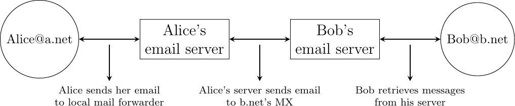
Before looking at the details of Internet email, let us consider a simple scenario illustrated in Fig. 28, where Alice sends an email to Bob. Alice prepares her email by using an email clients and sends it to her email server. Alice’s email server extracts Bob’s address from the email and delivers the message to Bob’s server. Bob retrieves Alice’s message on his server and reads it by using his favorite email client or through his webmail interface.
Fig. 28 Simplified architecture of the Internet email
The email system that we consider in this book is composed of four components :
a message format, that defines how valid email messages are encoded
protocols, that allow hosts and servers to exchange email messages
client software, that allows users to easily create and read email messages
software, that allows servers to efficiently exchange email messages
We first discuss the format of email messages followed by the protocols that are used on today’s Internet to exchange and retrieve emails. Other email systems have been developed in the past [Bush1993] [Genilloud1990] [GC2000], but today most email solutions have migrated to the Internet email. Information about the software that is used to compose and deliver emails may be found on wikipedia among others, for both email clients and email servers. More detailed information about the full Internet Mail Architecture may be found in RFC 5598.
Email messages, like postal mail, are composed of two parts :
a header that plays the same role as the letterhead in regular mail. It contains metadata about the message.
the body that contains the message itself.
Email messages are entirely composed of lines of ASCII characters. Each line can contain up to 998 characters and is terminated by the CR and LF control characters RFC 5322. The lines that compose the header appear before the message body. An empty line, containing only the CR and LF characters, marks the end of the header. This is illustrated in Fig. 29.
Fig. 29 The structure of email messages
The email header contains several lines that all begin with a keyword followed by a colon and additional information. The format of email messages and the different types of header lines are defined in RFC 5322. Two of these header lines are mandatory and must appear in all email messages :
The sender address. This header line starts with From:. This contains the (optional) name of the sender followed by its email address between < and >. Email addresses are always composed of a username followed by the @ sign and a domain name.
The date. This header line starts with Date:. RFC 5322 precisely defines the format used to encode a date.
Other header lines appear in most email messages. The Subject: header line allows the sender to indicate the topic discussed in the email. Three types of header lines can be used to specify the recipients of a message :
the To: header line contains the email addresses of the primary recipients of the message [10]. Several addresses can be separated by using commas.
the cc: header line is used by the sender to provide a list of email addresses that must receive a carbon copy of the message. Several addresses can be listed in this header line, separated by commas. All recipients of the email message receive the To: and cc: header lines.
the bcc: header line is used by the sender to provide a list of comma separated email addresses that must receive a blind carbon copy of the message. The bcc: header line is not delivered to the recipients of the email message.
A simple email message containing the From:, To:, Subject: and Date: header lines and two lines of body is shown below.
From: Bob Smith <Bob@machine.example>
To: Alice Doe <alice@example.net>, Alice Smith <Alice@machine.example>
Subject: Hello
Date: Mon, 8 Mar 2010 19:55:06 -0600

This is the "Hello world" of email messages.
This is the second line of the body
Note the empty line after the Date: header line; this empty line contains only the CR and LF characters, and marks the boundary between the header and the body of the message.
Several other optional header lines are defined in RFC 5322 and elsewhere [11]. Furthermore, many email clients and servers define their own header lines starting from X-. Several of the optional header lines defined in RFC 5322 are worth being discussed here :
the Message-Id: header line is used to associate a “unique” identifier to each email. Email identifiers are usually structured like string@domain where string is a unique character string or sequence number chosen by the sender of the email and domain the domain name of the sender. Since domain names are unique, a host can generate globally unique message identifiers concatenating a locally unique identifier with its domain name.
the In-reply-to: header line is used when a message was created in reply to a previous message. In this case, the end of the In-reply-to: line contains the identifier of the original message.
the Received: header line is used when an email message is processed by several servers before reaching its destination. Each intermediate email server adds a Received: header line. These header lines are useful to debug problems in delivering email messages.
The figure below shows the header lines of one email message. The message originated at a host named wira.firstpr.com.au and was received by smtp3.sgsi.ucl.ac.be. The Received: lines have been wrapped for readability.
Received: from smtp3.sgsi.ucl.ac.be (Unknown [10.1.5.3])
    by mmp.sipr-dc.ucl.ac.be
    (Sun Java(tm) System Messaging Server 7u3-15.01 64bit (built Feb 12 2010))
    with ESMTP id <0KYY00L85LI5JLE0@mmp.sipr-dc.ucl.ac.be>; Mon,
    08 Mar 2010 11:37:17 +0100 (CET)
Received: from mail.ietf.org (mail.ietf.org [64.170.98.32])
    by smtp3.sgsi.ucl.ac.be (Postfix) with ESMTP id B92351C60D7; Mon,
    08 Mar 2010 11:36:51 +0100 (CET)
Received: from [127.0.0.1] (localhost [127.0.0.1])     by core3.amsl.com (Postfix)
    with ESMTP id F066A3A68B9; Mon, 08 Mar 2010 02:36:38 -0800 (PST)
Received: from localhost (localhost [127.0.0.1])       by core3.amsl.com (Postfix)
    with ESMTP id A1E6C3A681B  for <rrg@core3.amsl.com>; Mon,
    08 Mar 2010 02:36:37 -0800 (PST)
Received: from mail.ietf.org ([64.170.98.32])
    by localhost (core3.amsl.com [127.0.0.1]) (amavisd-new, port 10024)
    with ESMTP id erw8ih2v8VQa for <rrg@core3.amsl.com>; Mon,
    08 Mar 2010 02:36:36 -0800 (PST)
Received: from gair.firstpr.com.au (gair.firstpr.com.au [150.101.162.123])
    by core3.amsl.com (Postfix) with ESMTP id 03E893A67ED      for <rrg@irtf.org>; Mon,
    08 Mar 2010 02:36:35 -0800 (PST)
Received: from [10.0.0.6] (wira.firstpr.com.au [10.0.0.6])
    by gair.firstpr.com.au (Postfix) with ESMTP id D0A49175B63; Mon,
    08 Mar 2010 21:36:37 +1100 (EST)
Date: Mon, 08 Mar 2010 21:36:38 +1100
From: Robin Whittle <rw@firstpr.com.au>
Subject: Re: [rrg] Recommendation and what happens next
In-reply-to: <C7B9C21A.4FAB%tony.li@tony.li>
To: RRG <rrg@irtf.org>
Message-id: <4B94D336.7030504@firstpr.com.au>

Message content removed
Initially, email was used to exchange small messages of ASCII text between computer scientists. However, with the growth of the Internet, supporting only ASCII text became a severe limitation for two reasons. First of all, non-English speakers wanted to write emails in their native language that often required more characters than those of the ASCII character table. Second, many users wanted to send other content than just ASCII text by email such as binary files, images or sound.
To solve this problem, the IETF developed the Multipurpose Internet Mail Extensions (MIME). These extensions were carefully designed to allow Internet email to carry non-ASCII characters and binary files without breaking the email servers that were deployed at that time. This requirement for backward compatibility forced the MIME designers to develop extensions to the existing email message format RFC 822 instead of defining a completely new format that would have been better suited to support the new types of emails.
RFC 2045 defines three new types of header lines to support MIME :
The MIME-Version: header line indicates the version of the MIME specification that was used to encode the email message. The current version of MIME is 1.0. Other versions of MIME may be defined in the future. Thanks to this header line, the software that processes email messages will be able to adapt to the MIME version used to encode the message. Messages that do not contain this header are supposed to be formatted according to the original RFC 822 specification.
The Content-Type: header line indicates the type of data that is carried inside the message (see below).
The Content-Transfer-Encoding: header line is used to specify how the message has been encoded. When MIME was designed, some email servers were only able to process messages containing characters encoded using the 7 bits ASCII character set. MIME allows the utilization of other character encodings.
Inside the email header, the Content-Type: header line indicates how the MIME email message is structured. RFC 2046 defines the utilization of this header line. The two most common structures for MIME messages are :
Content-Type: multipart/mixed. This header line indicates that the MIME message contains several independent parts. For example, such a message may contain a part in plain text and a binary file.
Content-Type: multipart/alternative. This header line indicates that the MIME message contains several representations of the same information. For example, a multipart/alternative message may contain both a plain text and an HTML version of the same text.
To support these two types of MIME messages, the recipient of a message must be able to extract the different parts from the message. In RFC 822, an empty line was used to separate the header lines from the body. Using an empty line to separate the different parts of an email body would be difficult as the body of email messages often contains one or more empty lines. Another possible option would be to define a special line, e.g. *-LAST_LINE-* to mark the boundary between two parts of a MIME message. Unfortunately, this is not possible as some emails may contain this string in their body (e.g. emails sent to students to explain the format of MIME messages). To solve this problem, the Content-Type: header line contains a second parameter that specifies the string that has been used by the sender of the MIME message to delineate the different parts. In practice, this string is often chosen randomly by the mail client.
The email message below, copied from RFC 2046 shows a MIME message containing two parts that are both in plain text and encoded using the ASCII character set. The string simple boundary is defined in the Content-Type: header as the marker for the boundary between two successive parts. Another example of MIME messages may be found in RFC 2046.
Date: Mon, 20 Sep 1999 16:33:16 +0200
From: Nathaniel Borenstein <nsb@bellcore.com>
To: Ned Freed <ned@innosoft.com>
Subject: Test
MIME-Version: 1.0
Content-Type: multipart/mixed; boundary="simple boundary"

preamble, to be ignored

--simple boundary
Content-Type: text/plain; charset=us-ascii

First part

--simple boundary
Content-Type: text/plain; charset=us-ascii

Second part
--simple boundary
The Content-Type: header can also be used inside a MIME part. In this case, it indicates the type of data placed in this part. Each data type is specified as a type followed by a subtype. A detailed description may be found in RFC 2046. Some of the most popular Content-Type: header lines are :
text. The message part contains information in textual format. There are several subtypes : text/plain for regular ASCII text, text/html defined in RFC 2854 for documents in HTML format or the text/enriched format defined in RFC 1896. The Content-Type: header line may contain a second parameter that specifies the character set used to encode the text. charset=us-ascii is the standard ASCII character table. Other frequent character sets include charset=UTF8 or charset=iso-8859-1. The list of standard character sets is maintained by IANA.
image. The message part contains a binary representation of an image. The subtype indicates the format of the image such as gif, jpg or png.
audio. The message part contains an audio clip. The subtype indicates the format of the audio clip like wav or mp3.
video. The message part contains a video clip. The subtype indicates the format of the video clip like avi or mp4.
application. The message part contains binary information that was produced by the particular application listed as the subtype. Email clients use the subtype to launch the application that is able to decode the received binary information.
Note
From ASCII to Unicode
The first computers used different techniques to represent characters in memory and on disk. During the 1960s, computers began to exchange information via tape or telephone lines. Unfortunately, each vendor had its own proprietary character set and exchanging data between computers from different vendors was often difficult. The 7 bits ASCII character table RFC 20 was adopted by several vendors and by many Internet protocols. However, ASCII became a problem with the internationalization of the Internet and the desire of more and more users to use character sets that support their own written language. A first attempt at solving this problem was the definition of the ISO-8859 character sets by ISO. This family of standards specified various character sets that allowed the representation of many European written languages by using 8 bits characters. Unfortunately, an 8-bits character set is not sufficient to support some widely used languages, such as those used in Asian countries. Fortunately, at the end of the 1980s, several computer scientists proposed to develop a standard that supports all written languages used on Earth today. The Unicode standard [Unicode] has now been adopted by most computer and software vendors. For example, Java always uses Unicode to manipulate characters, Python can handle both ASCII and Unicode characters. Internet applications are slowly moving towards complete support for the Unicode character sets, but moving from ASCII to Unicode is an important change that can have a huge impact on current deployed implementations. See, for example, the work to completely internationalize email RFC 4952 and domain names RFC 5890.
The last MIME header line is Content-Transfer-Encoding:. This header line is used after the Content-Type: header line, within a message part, and specifies how the message part has been encoded. The default encoding is to use 7 bits ASCII. The most frequent encodings are quoted-printable and Base64. Both support encoding a sequence of bytes into a set of ASCII lines that can be safely transmitted by email servers. quoted-printable is defined in RFC 2045. We briefly describe base64 which is defined in RFC 2045 and RFC 4648.
Base64 divides the sequence of bytes to be encoded into groups of three bytes (with the last group possibly being partially filled). Each group of three bytes is then divided into four six-bit fields and each six bit field is encoded as a character from the table below.
Value |
Encoding |
Value |
Encoding |
Value |
Encoding |
Value |
Encoding |
0 |
A |
17 |
R |
34 |
i |
51 |
z |
1 |
B |
18 |
S |
35 |
j |
52 |
0 |
2 |
C |
19 |
T |
36 |
k |
53 |
1 |
3 |
D |
20 |
U |
37 |
l |
54 |
2 |
4 |
E |
21 |
V |
38 |
m |
55 |
3 |
5 |
F |
22 |
W |
39 |
n |
56 |
4 |
6 |
G |
23 |
X |
40 |
o |
57 |
5 |
7 |
H |
24 |
Y |
41 |
p |
58 |
6 |
8 |
I |
25 |
Z |
42 |
q |
59 |
7 |
9 |
J |
26 |
a |
43 |
r |
60 |
8 |
10 |
K |
27 |
b |
44 |
s |
61 |
9 |
11 |
L |
28 |
c |
45 |
t |
62 |
+ |
12 |
M |
29 |
d |
46 |
u |
63 |
/ |
13 |
N |
30 |
e |
47 |
v |
||
14 |
O |
31 |
f |
48 |
w |
||
15 |
P |
32 |
g |
49 |
x |
||
16 |
Q |
33 |
h |
50 |
y |
The example below, from RFC 4648, illustrates the Base64 encoding.
Input data
0x14fb9c03d97e
8-bit
00010100 11111011 10011100 00000011 11011001 01111110
6-bit
000101 001111 101110 011100 000000 111101 100101 111110
Decimal
5 15 46 28 0 61 37 62
Encoding
F P u c A 9 l +
The last point to be discussed about base64 is what happens when the length of the sequence of bytes to be encoded is not a multiple of three. In this case, the last group of bytes may contain one or two bytes instead of three. Base64 reserves the = character as a padding character. This character is used once when the last group contains two bytes and twice when it contains one byte as illustrated by the two examples below.
Input data
0x14
8-bit
00010100
6-bit
000101 000000
Decimal
5 0
Encoding
F A = =
Input data
0x14b9
8-bit
00010100 11111011
6-bit
000101 001111 101100
Decimal
5 15 44
Encoding
F P s =
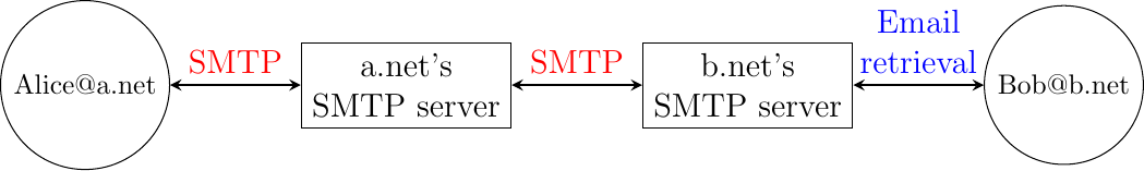
Now that we have explained the format of the email messages, we can discuss how these messages can be exchanged through the Internet. Fig. 30 illustrates the protocols that are used when Alice sends an email message to Bob. Alice prepares her email with an email client or on a webmail interface. To send her email to Bob, Alice’s client will use the Simple Mail Transfer Protocol (SMTP) to deliver her message to her SMTP server. Alice’s email client is configured with the name of the default SMTP server for her domain. There is usually at least one SMTP server per domain. To deliver the message, Alice’s SMTP server must find the SMTP server that contains Bob’s mailbox. This can be done by using the Mail eXchange (MX) records of the DNS. A set of MX records can be associated to each domain. Each MX record contains a numerical preference and the fully qualified domain name of a SMTP server that is able to deliver email messages destined to all valid email addresses of this domain. The DNS can return several MX records for a given domain. In this case, the server with the lowest numerical preference is used first RFC 2821. If this server is not reachable, the second most preferred server is used etc. Bob’s SMTP server will store the message sent by Alice until Bob retrieves it using a webmail interface or protocols such as the Post Office Protocol (POP) or the Internet Message Access Protocol (IMAP).
Fig. 30 Email delivery protocols
The Simple Mail Transfer Protocol#
The Simple Mail Transfer Protocol (SMTP) defined in RFC 5321 is a client-server protocol. The SMTP specification distinguishes between five types of processes involved in the delivery of email messages. Email messages are composed on a Mail User Agent (MUA). The MUA is usually either an email client or a webmail. The MUA sends the email message to a Mail Submission Agent (MSA). The MSA processes the received email and forwards it to the Mail Transmission Agent (MTA). The MTA is responsible for the transmission of the email, directly or via intermediate MTAs to the MTA of the destination domain. This destination MTA will then forward the message to the Mail Delivery Agent (MDA) where it will be accessed by the recipient’s MUA. SMTP is used for the interactions between MUA and MSA [12], MSA-MTA and MTA-MTA.
SMTP is a text-based protocol like many other application-layer protocols on the Internet. It relies on the byte-stream service. Servers listen on port 25. Clients send commands that are each composed of one line of ASCII text terminated by CR+LF. Servers reply by sending ASCII lines that contain a three digit numerical error/success code and optional comments.
The SMTP protocol, like most text-based protocols, is specified as a BNF. The full BNF is defined in RFC 5321. The main SMTP commands are defined by the BNF rules shown in Fig. 31.

Fig. 31 BNF specification of the SMTP commands#
In this BNF, atext corresponds to printable ASCII characters. This BNF rule is defined in RFC 5322. The five main commands are EHLO [13], MAIL FROM:, RCPT TO:, DATA and QUIT. Postmaster is the alias of the system administrator who is responsible for a given domain or SMTP server. All domains must have a Postmaster alias. The SMTP responses are defined by the BNF shown in Fig. 32.

Fig. 32 BNF specification of the SMTP responses#
SMTP servers use structured reply codes containing three digits and an optional comment. The first digit of the reply code indicates whether the command was successful or not. A reply code of 2xy indicates that the command has been accepted. A reply code of 3xy indicates that the command has been accepted, but additional information from the client is expected. A reply code of 4xy indicates a transient negative reply. This means that for some reason, which is indicated by either the other digits or the comment, the command cannot be processed immediately, but there is some hope that the problem will only be transient. This is basically telling the client to try the same command again later. In contrast, a reply code of 5xy indicates a permanent failure or error. In this case, it is useless for the client to retry the same command later. Other application layer protocols such as FTP RFC 959 or HTTP RFC 2616 use a similar structure for their reply codes. Additional details about the other reply codes may be found in RFC 5321.
Examples of SMTP reply codes include the following :
220  <domain> Service ready
221  <domain> Service closing transmission channel
250  Requested mail action okay, completed
354  Start mail input; end with <CRLF>.<CRLF>
421  <domain> Service not available, closing transmission channel
450  Requested mail action not taken: mailbox unavailable
452  Requested action not taken: insufficient system storage
500  Syntax error, command unrecognized
501  Syntax error in parameters or arguments
502  Command not implemented
503  Bad sequence of commands
550  Requested action not taken: mailbox unavailable
Reply code 220 is used by the server as the first message when it agrees to interact with the client. Reply code 221 is sent by the server before closing the underlying transport connection. Reply code 250 is the standard positive reply that indicates the success of the previous command. Reply code 354 indicates that the client can start transmitting its email message. Reply code 421 is returned when there is a problem (e.g. lack of memory/disk resources) that prevents the server from accepting the transport connection. Reply codes 450 and 452 indicate that the destination mailbox is temporarily unavailable, for various reasons, while reply code 550 indicates that the mailbox does not exist or cannot be used for policy reasons. The 500 to 503 reply codes correspond to errors in the commands sent by the client. The 503 reply code would be sent by the server when the client sends commands in an incorrect order (e.g. the client tries to send an email before providing the destination address of the message).
The transfer of an email message is performed in three phases. During the first phase, the client opens a transport connection with the server. Once the connection has been established, the client and the server exchange greetings messages (EHLO command). Most servers insist on receiving valid greeting messages and some of them drop the underlying transport connection if they do not receive a valid greeting. Once the greetings have been exchanged, the email transfer phase can start. During this phase, the client transfers one or more email messages by indicating the email address of the sender (MAIL FROM: command), the email address of the recipient (RCPT TO: command) followed by the headers and the body of the email message (DATA command). Once the client has finished sending all its queued email messages to the SMTP server, it terminates the SMTP association (QUIT command).
A successful transfer of an email message is shown below
S: 220 smtp.example.com ESMTP MTA information
C: EHLO mta.example.org
S: 250 Hello mta.example.org, glad to meet you
C: MAIL FROM:<alice@example.org>
S: 250 Ok
C: RCPT TO:<bob@example.com>
S: 250 Ok
C: DATA
S: 354 End data with <CR><LF>.<CR><LF>
C: From: "Alice Doe" <alice@example.org>
C: To: Bob Smith <bob@example.com>
C: Date: Mon, 9 Mar 2010 18:22:32 +0100
C: Subject: Hello
C:
C: Hello Bob
C: This is a small message containing 4 lines of text.
C: Best regards,
C: Alice
C: .
S: 250 Ok: queued as 12345
C: QUIT
S: 221 Bye
In the example above, the MTA running on mta.example.org opens a TCP connection to the SMTP server on host smtp.example.com. The lines prefixed with S: (resp. C:) are the responses sent by the server (resp. the commands sent by the client). The server sends its greetings as soon as the TCP connection has been established. The client then sends the EHLO command with its fully qualified domain name. The server replies with reply-code 250 and sends its greetings. The SMTP association can now be used to exchange an email.
To send an email, the client must first provide the address of the recipient with RCPT TO:. Then it uses the MAIL FROM: with the address of the sender. Both the recipient and the sender are accepted by the server. The client can now issue the DATA command to start the transfer of the email message. After having received the 354 reply code, the client sends the headers and the body of its email message. The client indicates the end of the message by sending a line containing only the . (dot) character [14]. The server confirms that the email message has been queued for delivery or transmission with a reply code of 250. The client issues the QUIT command to close the session and the server confirms with reply-code 221, before closing the TCP connection.
Note
Open SMTP relays and spam
Since its creation in 1971, email has been a very useful tool that is used by many users to exchange lots of information. In the early days, all SMTP servers were open and anyone could use them to forward emails towards their final destination. Unfortunately, over the years, some unscrupulous users have found ways to use email for marketing purposes or to send malware. The first documented abuse of email for marketing purposes occurred in 1978 when a marketer who worked for a computer vendor sent a marketing email to many ARPANET users. At that time, the ARPANET could only be used for research purposes and this was an abuse of the acceptable use policy. Unfortunately, given the extremely low cost of sending emails, the problem of unsolicited emails has not stopped. Unsolicited emails are now called spam and a study carried out by ENISA in 2009 reveals that 95% of email was spam and this number seems to continue to grow. This places a burden on the email infrastructure of Internet Service Providers and large companies that need to process many useless messages.
Given the amount of spam messages, SMTP servers are no longer open RFC 5068. Several extensions to SMTP have been developed in recent years to deal with this problem. For example, the SMTP authentication scheme defined in RFC 4954 can be used by an SMTP server to authenticate a client. Several techniques have also been proposed to allow SMTP servers to authenticate the messages sent by their users RFC 4870 RFC 4871 .
The Post Office Protocol#
When the first versions of SMTP were designed, the Internet was composed of minicomputers that were used by an entire university department or research lab. These minicomputers were used by many users at the same time. Email was mainly used to send messages from a user on a given host to another user on a remote host. At that time, SMTP was the only protocol involved in the delivery of the emails as all hosts attached to the network were running an SMTP server. On such hosts, an email destined to local users was delivered by placing the email in a special directory or file owned by the user. However, the introduction of personal computers in the 1980s changed this environment. Initially, users of these personal computers used applications such as telnet to open a remote session on the local minicomputer to read their email. This was not user-friendly. A better solution appeared with the development of user friendly email client applications on personal computers. Several protocols were designed to allow these client applications to retrieve the email messages destined to a user from his/her server. Two of these protocols became popular and are still used today. The Post Office Protocol (POP), defined in RFC 1939, is the simplest one. It allows a client to download all the messages destined to a given user from his/her email server. We describe POP briefly in this section. The second protocol is the Internet Message Access Protocol (IMAP), defined in RFC 3501. IMAP is more powerful, but also more complex than POP. IMAP was designed to allow client applications to efficiently access, in real-time, to messages stored in various folders on servers. IMAP assumes that all the messages of a given user are stored on a server and provides the functions that are necessary to search, download, delete or filter messages.
POP is another example of a simple line-based protocol. POP runs above the bytestream service. A POP server usually listens to port 110. A POP session is composed of three parts : an authorisation phase during which the server verifies the client’s credential, a transaction phase during which the client downloads messages and an update phase that concludes the session. The client sends commands and the server replies are prefixed by +OK to indicate a successful command or by -ERR to indicate errors.
When a client opens a transport connection with the POP server, the latter sends as banner an ASCII-line starting with +OK. The POP session is at that time in the authorisation phase. In this phase, the client can send its username (resp. password) with the USER (resp. PASS) command. The server replies with +OK if the username (resp. password) is valid and -ERR otherwise.
Once the username and password have been validated, the POP session enters in the transaction phase. In this phase, the client can issue several commands. The STAT command is used to retrieve the status of the server. Upon reception of this command, the server replies with a line that contains +OK followed by the number of messages in the mailbox and the total size of the mailbox in bytes. The RETR command, followed by a space and an integer, is used to retrieve the nth message of the mailbox. The DELE command is used to mark for deletion the nth message of the mailbox.
Once the client has retrieved and possibly deleted the emails contained in the mailbox, it must issue the QUIT command. This command terminates the POP session and allows the server to delete all the messages that have been marked for deletion by using the DELE command.
The figure below provides a simple POP session. All lines prefixed with C: (resp. S:) are sent by the client (resp. server).
S:    +OK POP3 server ready
C:    USER alice
S:    +OK
C     PASS 12345pass
S:    +OK alice's maildrop has 2 messages (620 octets)
C:    STAT
S:    +OK 2 620
C:    LIST
S:    +OK 2 messages (620 octets)
S:    1 120
S:    2 500
S:    .
C:    RETR 1
S:    +OK 120 octets
S:    <the POP3 server sends message 1>
S:    .
C:    DELE 1
S:    +OK message 1 deleted
C:    QUIT
S:    +OK POP3 server signing off (1 message left)
In this example, a POP client contacts a POP server on behalf of the user named alice. Note that in this example, Alice’s password is sent in clear by the client. This implies that if someone is able to capture the packets sent by Alice, he will know Alice’s password [15]. Then Alice’s client issues the STAT command to know the number of messages that are stored in her mailbox. It then retrieves and deletes the first message of the mailbox.
The world wide web#
In the early days, the Internet was mainly used for remote terminal access with telnet, email and file transfer. The default file transfer protocol, FTP, defined in RFC 959 was widely used. FTP clients and servers are still included in some operating systems.
Many FTP clients offered a user interface similar to a Unix shell and allowed clients to browse the file system on the server and to send and retrieve files. FTP servers can be configured in two modes :
authenticated : in this mode, the ftp server only accepts users with a valid user name and password. Once authenticated, they can access the files and directories according to their permissions
anonymous : in this mode, clients supply the anonymous user identifier and their email address as password. These clients are granted access to a special zone of the file system that only contains public files.
FTP was very popular in the 1990s and early 2000s, but today it has mostly been superseded by more recent protocols. Authenticated access to files is mainly done by using the Secure Shell (ssh) protocol defined in RFC 4251 and supported by clients such as scp or sftp. Nowadays, anonymous access is mainly provided by web protocols.
In the late 1980s, high energy physicists working at CERN had to efficiently exchange documents about their ongoing and planned experiments. Tim Berners-Lee evaluated several of the documents sharing techniques that were available at that time [B1989]. As none of the existing solutions met CERN’s requirements, they chose to develop a completely new document sharing system. This system was initially called the mesh. It was quickly renamed the world wide web. The starting point for the world wide web are hypertext documents. An hypertext document is a document that contains references (hyperlinks) to other documents that the reader can immediately access. Hypertext was not invented for the world wide web. The idea of hypertext documents was proposed in 1945 [Bush1945] and the first experiments were done during the 1960s [Nelson1965] [Myers1998] . Compared to the hypertext documents that were used in the late 1980s, the main innovation introduced by the world wide web was to allow hyperlinks to reference documents stored on different remote machines. This is illustrated in Fig. 33.
Fig. 33 World-wide web clients and servers
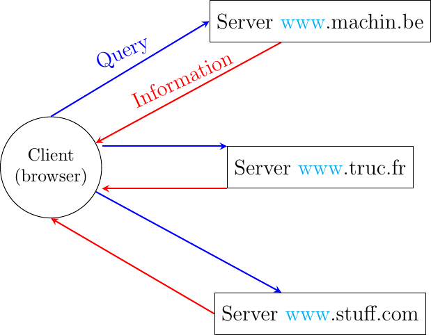
A document sharing system such as the world wide web is composed of three important parts.
A standardized addressing scheme that unambiguously identifies documents
A standard document format : the HyperText Markup Language
A standardized protocol to efficiently retrieve the documents stored on a server
Note
Open standards and open implementations
Open standards play a key role in the success of the world wide web as we know it today. Without open standards, the world wide web would have never reached its current size. In addition to open standards, another important factor for the success of the web was the availability of open and efficient implementations of these standards. When CERN started to work on the web, their objective was to build a running system that could be used by physicists. They developed open-source implementations of the first web servers and web clients. These open-source implementations were powerful and could be used as is, by institutions willing to share information. They were also extended by other developers who contributed to new features. For example, the NCSA added support for images in their Mosaic browser that was eventually used to create Netscape Communications and the first commercial browsers and servers.
The first components of the world wide web are the Uniform Resource Identifiers (URI), defined in RFC 3986. A URI is a character string that unambiguously identifies a resource on the world wide web. Here is a subset of the BNF for URIs
URI           = scheme ":" "//" authority path [ "?" query ] [ "#" fragment ]
scheme        = ALPHA *( ALPHA / DIGIT / "+" / "-" / "." )
authority     = [ userinfo "@" ] host [ ":" port ]
query         = *( pchar / "/" / "?" )
fragment      = *( pchar / "/" / "?" )
pchar         = unreserved / pct-encoded / sub-delims / ":" / "@"
query         = *( pchar / "/" / "?" )
fragment      = *( pchar / "/" / "?" )
pct-encoded   = "%" HEXDIG HEXDIG
unreserved    = ALPHA / DIGIT / "-" / "." / "_" / "~"
reserved      = gen-delims / sub-delims
gen-delims    = ":" / "/" / "?" / "#" / "[" / "]" / "@"
sub-delims    = "!" / "$" / "&" / "'" / "(" / ")" / "*" / "+" / "," / ";" / "="
The first component of a URI is its scheme. A scheme can be seen as a selector, indicating the meaning of the fields after it. In practice, the scheme often identifies the application-layer protocol that must be used by the client to retrieve the document, but it is not always the case. Some schemes do not imply a protocol at all and some do not indicate a retrievable document [16]. The most frequent schemes are http and https. We focus on http in this section. A URI scheme can be defined for almost any application layer protocol [17]. The characters : and // follow the scheme of any URI.
The second part of the URI is the authority. With retrievable URIs, this includes the DNS name or the IP address of the server where the document can be retrieved using the protocol specified via the scheme. This name can be preceded by some information about the user (e.g. a user name) who is requesting the information. Earlier definitions of the URI allowed the specification of a user name and a password before the @ character (RFC 1738), but this is now deprecated as placing a password inside a URI is insecure. The host name can be followed by the semicolon character and a port number. A default port number is defined for some protocols and the port number should only be included in the URI if a non-default port number is used (for other protocols, techniques like service DNS records can used).
The third part of the URI is the path to the document. This path is structured as filenames on a Unix host (but it does not imply that the files are indeed stored this way on the server). If the path is not specified, the server will return a default document. The last two optional parts of the URI are used to provide a query parameter and indicate a specific part (e.g. a section in an article) of the requested document. Sample URIs are shown below.
http://tools.ietf.org/html/rfc3986.html
mailto:infobot@example.com?subject=current-issue
http://docs.python.org/library/basehttpserver.html?highlight=http#BaseHTTPServer.BaseHTTPRequestHandler
telnet://[2001:db8:3080:3::2]:2323/
ftp://cnn.example.com&story=breaking_news@10.0.0.1/top_story.htm
The first URI corresponds to a document named rfc3986.html that is stored on the server named tools.ietf.org and can be accessed by using the http protocol on its default port. The second URI corresponds to an email message, with subject current-issue, that will be sent to user infobot in domain example.com. The mailto: URI scheme is defined in RFC 2368. The third URI references the portion BaseHTTPServer.BaseHTTPRequestHandler of the document basehttpserver.html that is stored in the library directory on the docs.python.org server. This document can be retrieved by using the http protocol. The query parameter highlight=http is associated to this URI. The fourth example is a server that operates the telnet protocol, uses IPv6 address 2001:db8:3080:3::2 and is reachable on port 2323. The last URI is somewhat special. Most users will assume that it corresponds to a document stored on the cnn.example.com server. However, to parse this URI, it is important to remember that the @ character is used to separate the user name from the host name in the authorization part of a URI. This implies that the URI points to a document named top_story.htm on the host having IPv4 address 10.0.0.1. The document will be retrieved by using the ftp protocol with the user name set to cnn.example.com&story=breaking_news.
The second component of the word wide web is the HyperText Markup Language (HTML). HTML defines the format of the documents that are exchanged on the web. The first version of HTML was derived from the Standard Generalized Markup Language (SGML) that was standardized in 1986 by ISO. SGML was designed to support large documents maintained by government, law firms or aerospace companies that must be shared efficiently in a machine-readable manner. These industries require documents to remain readable and editable for tens of years and insisted on a standardized format supported by multiple vendors. Today, SGML is no longer widely used beyond specific applications, but its descendants including HTML and XML are now widespread.
A markup language is a structured way of adding annotations about the formatting of the document within the document itself. Example markup languages include troff, which is used to write the Unix man pages or Latex. HTML uses markers to annotate text and a document is composed of HTML elements. Each element is usually composed of three parts: a start tag that potentially includes some specific attributes, some text (often including other elements), and an end tag. A HTML tag is a keyword enclosed in angle brackets. The generic form of an HTML element is
<tag>Some text to be displayed</tag>
More complex HTML elements can also include optional attributes in the start tag
<tag attribute1="value1" attribute2="value2">some text to be displayed</tag>
The HTML document shown in Fig. 34 is composed of two parts: a header, delineated by the <head> and </head> markers, and a body (between the <body> and </body> markers). In the example below, the header only contains a title, but other types of information can be included in the header. The body contains an image, some text and a list with three hyperlinks. The image is included in the web page by indicating its URI between brackets inside the <img src=”…”> marker. It is important to note that the image can reside on any server. The client will automatically download it when rendering the web page. The <h1>…</h1> marker is used to specify the first level of headings. The <ul> marker indicates an unnumbered list while the <li> marker indicates a list item. The <a href=”URI”>text</a> indicates a hyperlink. The text will be underlined in the rendered web page and the client will fetch the specified URI when the user clicks on the link.
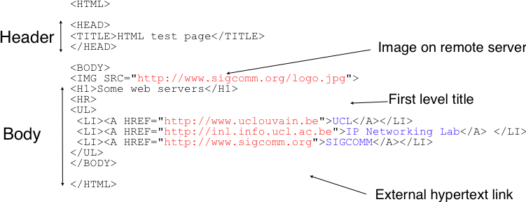
Fig. 34 A simple HTML page#
Over the years, various extensions to HTML have been proposed and implemented. These include the specification of style sheets that adjust the layout of the document and the possibility of adding or referencing javascript code. Additional details about the various extensions to HTML may be found in the official specifications maintained by W3C.
The HyperText Transfer Protocol#
The third component of the world wide web is the HyperText Transfer Protocol (HTTP). HTTP is a text-based protocol like SMTP. The client sends a request and the server returns a response. HTTP runs above the bytestream service and HTTP servers listen by default on port 80. The design of HTTP has largely been inspired by the Internet email protocols. Each HTTP request contains three parts :
a method, that indicates the type of request, a URI, and the version of the HTTP protocol used by the client
a header, that is used by the client to specify optional parameters for the request. An empty line is used to mark the end of the header
an optional MIME document attached to the request
The response sent by the server also contains three parts :
a status line , that indicates whether the request was successful or not
a header, that contains additional information about the response. The response header ends with an empty line.
a MIME document
Figure Fig. 35 provides sample HTTP request and response.
Fig. 35 HTTP requests and responses
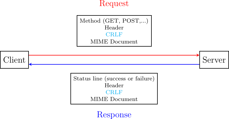
Several types of method can be used in HTTP requests. The three most important ones are :
the GET method is the most popular one. It is used to retrieve a document from a server. The GET method is encoded as GET followed by the path of the URI of the requested document and the version of HTTP used by the client. For example, to retrieve the http://www.w3.org/MarkUp/ URI, a client must open a TCP connection on port 80 with host www.w3.org and send a HTTP request containing the following line:
GET /MarkUp/ HTTP/1.0
the HEAD method is a variant of the GET method that allows the retrieval of the header lines for a given URI without retrieving the entire document. It can be used by a client to verify if a document exists, for instance.
the POST method can be used by a client to send a document to a server. The document is attached to the HTTP request as a MIME document.
HTTP clients and servers can include different HTTP headers in HTTP requests and responses. Each HTTP header is encoded as a single ASCII-line terminated by CR and LF. Several of these headers are briefly described below. A detailed discussion of the standard headers may be found in RFC 1945. The MIME headers can appear in both HTTP requests and HTTP responses.
the Content-Length: header is the MIME header that indicates the length of the MIME document in bytes.
the Content-Type: header is the MIME header that indicates the type of the attached MIME document. HTML pages use the text/html type.
the Content-Encoding: header indicates how the MIME document has been encoded. For example, this header would be set to x-gzip for a document compressed using the gzip software.
RFC 1945 and RFC 2616 define headers that are specific to HTTP responses. These server headers include:
the Server: header indicates the version of the web server that has generated the HTTP response. Some servers provide information about their software release and optional modules that they use. For security reasons, some system administrators disable these headers to avoid revealing too much information about their server to potential attackers.
the Date: header indicates when the HTTP response has been produced by the server.
the Last-Modified: header indicates the date and time of the last modification of the document attached to the HTTP response.
Similarly, the following header lines can only appear inside HTTP requests sent by a client:
the User-Agent: header provides information about the client that has generated the HTTP request. Some servers analyze this header line and return different headers and sometimes different documents for different user agents.
the If-Modified-Since: header is followed by a date. It enables clients to cache in memory or on disk recent or most frequently used documents. When a client needs to request a URI from a server, it first checks whether the document is already in its cache. If it is, the client sends an HTTP request with the If-Modified-Since: header indicating the date of the cached document. The server will only return the document attached to the HTTP response if it is newer than the version stored in the client’s cache.
the Referrer: header is followed by a URI. It indicates the URI of the document that the client visited before sending this HTTP request. Thanks to this header, the server can know the URI of the document containing the hyperlink followed by the client, if any. This information is very useful to measure the impact of advertisements containing hyperlinks placed on websites.
the Host: header contains the fully qualified domain name of the URI being requested.
Note
The importance of the Host: header line
The first version of HTTP did not include the Host: header line. This was a severe limitation for web hosting companies. For example consider a web hosting company that wants to serve both web.example.com and www.example.net on the same physical server. Both web sites contain a /index.html document. When a client sends a request for either http://web.example.com/index.html or http://www.example.net/index.html, the HTTP 1.0 request contains the following line :
GET /index.html HTTP/1.0
By parsing this line, a server cannot determine which index.html file is requested. Thanks to the Host: header line, the server knows whether the request is for http://web.example.com/index.html or http://www.dummy.net/index.html. Without the Host: header, this is impossible. The Host: header line allowed web hosting companies to develop their business by supporting a large number of independent web servers on the same physical server.
The status line of the HTTP response begins with the version of HTTP used by the server (usually HTTP/1.0 defined in RFC 1945 or HTTP/1.1 defined in RFC 2616) followed by a three digit status code and additional information in English. HTTP status codes have a similar structure as the reply codes used by SMTP:
All status codes starting with digit 2 indicate a valid response. 200 Ok indicates that the HTTP request was successfully processed by the server and that the response is valid.
All status codes starting with digit 3 indicate that the requested document is no longer available on the server. 301 Moved Permanently indicates that the requested document is no longer available on this server. A Location: header containing the new URI of the requested document is inserted in the HTTP response. 304 Not Modified is used in response to an HTTP request containing the If-Modified-Since: header. This status line is used by the server if the document stored on the server is not more recent than the date indicated in the If-Modified-Since: header.
All status codes starting with digit 4 indicate that the server has detected an error in the HTTP request sent by the client. 400 Bad Request indicates a syntax error in the HTTP request. 404 Not Found indicates that the requested document does not exist on the server.
All status codes starting with digit 5 indicate an error on the server. 500 Internal Server Error indicates that the server could not process the request due to an error on the server itself.
In both HTTP requests and responses, the MIME document refers to a representation of the document with the MIME headers indicating the type of document and its size.
As an illustration of HTTP/1.0, the transcript below shows a HTTP request for http://www.ietf.org and the corresponding HTTP response. The HTTP request was sent using the curl command line tool. The User-Agent: header line contains more information about this client software. There is no MIME document attached to this HTTP request, and it ends with a blank line.
GET / HTTP/1.0
User-Agent: curl/7.19.4 (universal-apple-darwin10.0) libcurl/7.19.4 OpenSSL/0.9.8l zlib/1.2.3
Host: www.ietf.org
The HTTP response indicates the version of the server software used with the modules included. The Last-Modified: header indicates that the requested document was modified about one week before the request. A HTML document (not shown) is attached to the response. Note the blank line between the header of the HTTP response and the attached MIME document. The Server: header line has been truncated in this output.
HTTP/1.1 200 OK
Date: Mon, 15 Mar 2010 13:40:38 GMT
Server: Apache/2.2.4 (Linux/SUSE) mod_ssl/2.2.4 OpenSSL/0.9.8e (truncated)
Last-Modified: Tue, 09 Mar 2010 21:26:53 GMT
Content-Length: 17019
Content-Type: text/html

<!DOCTYPE HTML PUBLIC .../HTML>
HTTP was initially designed to share text documents. For this reason, and to ease the implementation of clients and servers, the designers of HTTP chose to open a TCP connection for each HTTP request. This implies that a client must open one TCP connection for each URI that it wants to retrieve from a server as illustrated on the figure below, showing HTTP 1.0 and the underlying TCP connection. For a web page containing only text documents this was a reasonable design choice as the client usually remains idle while the (human) user is reading the retrieved document.
![msc {
a1 [label="", linecolour=white],
a [label="", linecolour=white],
b [label="Client", linecolour=black],
z [label="", linecolour=white],
c [label="Server", linecolour=black],
d [label="", linecolour=white],
d1 [label="", linecolour=white];
a1=>b [ label = "CONNECT.request" ] ,
b>>c [ label = "", arcskip="1"];
c=>d1 [ label = "CONNECT.indication" ];
d1=>c [ label = "CONNECT.response" ] ,
c>>b [ label = "", arcskip="1"];
b=>a1 [ label = "CONNECT.confirm" ];
a1=>b [ label = "DATA.request(Request)", linecolour=red, textcolour=red],
b>>c [ linecolour=red, arcskip="1"];
c==d1 [ label = "DATA.indication(Request)", linecolour=red, textcolour=red];
d1=>c [ label = "DATA.request(Response)", linecolour=blue, textcolour=blue] ,
c>>b [ linecolour=blue, arcskip="1"];
b=>a1 [ label = "DATA.indication(Response)", linecolour=blue, textcolour=blue],
d1=>c [ label = "DISCONNECT.request"],
c>>b [ arcskip="1"];
b=>a1 [ label = "DISCONNECT.indication" ];
a1=>b [ label = "DISCONNECT.request" ] ,
b>>c [ label = "", arcskip="1"];
c=>d1 [ label = "DISCONNECT.indication" ];
}](../_images/mscgen-d49bedba389123d38d35a1fef746a30e5445ef03.png)
However, as the web evolved to support richer documents containing images, opening a TCP connection for each URI became a performance problem [Mogul1995]. Indeed, besides its HTML part, a web page may include dozens of images or more. Forcing the client to open a TCP connection for each component of a web page has two important drawbacks. First, the client and the server must exchange packets to open and close a TCP connection as we will see later. This increases the network overhead and the total delay of completely retrieving all the components of a web page. Second, a large number of established TCP connections may be a performance bottleneck on servers.
This problem was solved by extending HTTP to support persistent TCP connections RFC 2616. A persistent connection is a TCP connection over which a client may send several HTTP requests. This is illustrated in the figure below showing the persistent connection of HTTP 1.1.
![msc {
a1 [label="", linecolour=white],
a [label="", linecolour=white],
b [label="Client", linecolour=black],
z [label="", linecolour=white],
c [label="Server", linecolour=black],
d [label="", linecolour=white],
d1 [label="", linecolour=white];
a1=>b [ label = "CONNECT.request" ] ,
b>>c [ label = "", arcskip="1"];
c=>d1 [ label = "CONNECT.indication" ];
d1=>c [ label = "CONNECT.response" ] ,
c>>b [ label = "", arcskip="1"];
b=>a1 [ label = "CONNECT.confirm" ];
a1=>b [ label = "", linecolour=red, textcolour=red],
b>>c [ linecolour=red, arcskip="1"];
a1=>b [ label = "GET / HTTP1.1\nConnection: Keep-Alive\n...", linecolour=white, textcolour=red],
c=>d1 [ label = "", linecolour=red, textcolour=red];
d1=>c [ label = "", linecolour=blue, textcolour=blue] ,
c>>b [ linecolour=blue, arcskip="1"];
d1=>c [ label = "HTTP/1.1 200 OK\nKeep-Alive: timeout=15, max=100\nConnection: Keep-Alive\n...", linecolour=white, textcolour=blue],
b=>a1 [ label = "", linecolour=blue, textcolour=blue];
a1=>b [ label = "", linecolour=red, textcolour=red],
b>>c [ linecolour=red, arcskip="1"];
a1=>b [ label = "GET /images/logo.gif HTTP1.1\nConnection: Keep-Alive\n...", linecolour=white, textcolour=red],
c=>d1 [ label = "", linecolour=red, textcolour=red];
d1=>c [ label = "", linecolour=blue, textcolour=blue] ,
c>>b [ linecolour=blue, arcskip="1"];
d1=>c [ label = "HTTP/1.1 200 OK\nKeep-Alive: timeout=15, max=99\nConnection: Keep-Alive\n...", linecolour=white, textcolour=blue],
b=>a1 [ label = "", linecolour=blue, textcolour=blue];
|||;
d1=>c [ label = "DISCONNECT.request"],
c>>b [ arcskip="1"];
b=>a1 [ label = "DISCONNECT.indication" ];
a1=>b [ label = "DISCONNECT.request" ] ,
b>>c [ label = "", arcskip="1"];
c=>d1 [ label = "DISCONNECT.indication" ];
}](../_images/mscgen-e3a7f46f483e3da6d68605217fa3410d14c6e31b.png)
To allow the clients and servers to control the utilization of these persistent TCP connections, HTTP 1.1 RFC 2616 defines several new HTTP headers:
The Connection: header is used with the Keep-Alive argument by the client to indicate that it expects the underlying TCP connection to be persistent. When this header is used with the Close argument, it indicates that the entity that sent it will close the underlying TCP connection at the end of the HTTP response.
The Keep-Alive: header is used by the server to inform the client about how it agrees to use the persistent connection. A typical Keep-Alive: contains two parameters: the maximum number of requests that the server agrees to serve on the underlying TCP connection and the timeout (in seconds) after which the server will close an idle connection
The example below shows the operation of HTTP/1.1 over a persistent TCP connection to retrieve three URIs stored on the same server. Once the connection has been established, the client sends its first request with the Connection: Keep-Alive header to request a persistent connection.
GET / HTTP/1.1
Host: www.kame.net
User-Agent: Mozilla/5.0 (Macintosh; U; Intel Mac OS X 10_6_2; en-us)
Connection: Keep-Alive
The server replies with the Connection: Keep-Alive header and indicates that it accepts a maximum of 100 HTTP requests over this connection and that it will close the connection if it remains idle for 15 seconds.
HTTP/1.1 200 OK
Date: Fri, 19 Mar 2010 09:23:37 GMT
Server: Apache/2.0.63 (FreeBSD) PHP/5.2.12 with Suhosin-Patch
Keep-Alive: timeout=15, max=100
Connection: Keep-Alive
Content-Length: 3462
Content-Type: text/html

<html>...   </html>
The client sends a second request for the style sheet of the retrieved web page.
GET /style.css HTTP/1.1
Host: www.kame.net
Referer: http://www.kame.net/
User-Agent: Mozilla/5.0 (Macintosh; U; Intel Mac OS X 10_6_2; en-us)
Connection: keep-alive
The server replies with the requested style sheet and maintains the persistent connection. Note that the server only accepts 99 remaining HTTP requests over this persistent connection.
HTTP/1.1 200 OK
Date: Fri, 19 Mar 2010 09:23:37 GMT
Server: Apache/2.0.63 (FreeBSD) PHP/5.2.12 with Suhosin-Patch
Last-Modified: Mon, 10 Apr 2006 05:06:39 GMT
Content-Length: 2235
Keep-Alive: timeout=15, max=99
Connection: Keep-Alive
Content-Type: text/css

...
Then the client requested the web server’s icon [18]. This server does not contain such an icon and thus replies with a 404 HTTP status. However, the underlying TCP connection is not closed immediately.
GET /favicon.ico HTTP/1.1
Host: www.kame.net
Referer: http://www.kame.net/
User-Agent: Mozilla/5.0 (Macintosh; U; Intel Mac OS X 10_6_2; en-us)
Connection: keep-alive

HTTP/1.1 404 Not Found
Date: Fri, 19 Mar 2010 09:23:40 GMT
Server: Apache/2.0.63 (FreeBSD) PHP/5.2.12 with Suhosin-Patch
Content-Length: 318
Keep-Alive: timeout=15, max=98
Connection: Keep-Alive
Content-Type: text/html; charset=iso-8859-1

<!DOCTYPE HTML PUBLIC "-//IETF//DTD HTML 2.0//EN"> ...
As illustrated above, a client can send several HTTP requests over the same persistent TCP connection. However, it is important to note that all of these HTTP requests are considered to be independent by the server. Each HTTP request must be self-contained. This implies that each request must include all the header lines that are required by the server to understand the request. The independence of these requests is one of the key design choices of HTTP. As a consequence of this design choice, when a server processes a HTTP request, it does not use any other information than what is contained in the request itself. This explains why the client adds its User-Agent: header in all of the HTTP requests that it sends over the persistent TCP connection.
However, in practice, some servers want to provide content tuned for each user. For example, some servers can provide information in several languages. Other servers want to provide advertisements that are targeted to different types of users. To do this, servers need to maintain some information about the preferences of each user and use this information to produce content matching the user’s preferences. HTTP contains several mechanisms to solve this problem. We discuss three of them below.
A first solution is to force the users to be authenticated. This was the solution used by FTP to control the files that each user could access. Initially, user names and passwords could be included inside URIs RFC 1738. However, placing passwords in the clear in a potentially publicly visible URI is completely insecure and this usage has now been deprecated RFC 3986. HTTP supports several extension headers RFC 2617 that can be used by a server to request the authentication of the client by providing his/her credentials. However, user names and passwords have not been popular on web servers as they force human users to remember one user name and one password per server. Remembering a password is acceptable when a user needs to access protected content, but users will not accept to remember a unique user name and password for each web sites that they visit.
A second solution to allow servers to tune that content to the needs and capabilities of the user is to rely on the different types of Accept-* HTTP headers. For example, the Accept-Language: header can be used by the client to indicate its preferred languages. Unfortunately, in practice this header is usually set based on the default language of the browser and it is difficult for a user to indicate the language it prefers by selecting options for each visited web server.
The third and widely adopted solution are HTTP cookies. HTTP cookies were initially developed as a private extension by Netscape. They are now part of the standard RFC 6265. In a nutshell, a cookie is a short string that is chosen by a server to represent a given client. Two HTTP headers are used : Cookie: and Set-Cookie:. When a server receives an HTTP request from a new client (i.e. an HTTP request that does not contain the Cookie: header), it generates a cookie for the client and includes it in the Set-Cookie: header of the returned HTTP response. The Set-Cookie: header contains several additional parameters including the domain names for which the cookie is valid. The client stores all received cookies on disk and every time it sends an HTTP request, it verifies whether it already knows a cookie for this domain. If so, it attaches the Cookie: header to the HTTP request. This is illustrated in the figure below with HTTP 1.1, but cookies also work with HTTP 1.0.
![msc {
a1 [label="", linecolour=white],
a [label="", linecolour=white],
b [label="Client", linecolour=black],
z [label="", linecolour=white],
c [label="Server", linecolour=black],
d [label="", linecolour=white],
d1 [label="", linecolour=white];
a1=>b [ label = "", linecolour=red, textcolour=red],
b>>c [ linecolour=red, arcskip="1"];
a1=>b [ label = "GET / HTTP1.1\n...", linecolour=white, textcolour=red],
c=>d1 [ label = "", linecolour=red, textcolour=red];
d1=>c [ label = "", linecolour=blue, textcolour=blue] ,
c>>b [ linecolour=blue, arcskip="1"];
d1=>c [ label = "HTTP/1.1 200 OK\nSet-Cookie: machin\n...", linecolour=white, textcolour=blue],
b=>a1 [ label = "", linecolour=blue, textcolour=blue];
a1=>b [ label = "Browser saves cookie", linecolour=white],
c=>d1 [ label = "Normal response", linecolour=white];
a1=>b [ label = "", linecolour=red, textcolour=red],
b>>c [ linecolour=red, arcskip="1"];
a1=>b [ label = "GET /doc HTTP1.1\nCookie: machin\n...", linecolour=white, textcolour=red],
c=>d1 [ label = "", linecolour=red, textcolour=red];
d1=>c [ label = "", linecolour=blue, textcolour=blue] ,
c>>b [ linecolour=blue, arcskip="1"];
d1=>c [ label = "HTTP/1.1 200 OK\n...", linecolour=white, textcolour=blue],
b=>a1 [ label = "", linecolour=blue, textcolour=blue];
c=>d1 [ label = "Response is function\nof URL and cookie", linecolour=white];
a1=>b [ label = "", linecolour=red, textcolour=red],
b>>c [ linecolour=red, arcskip="1"];
a1=>b [ label = "GET /images/t.gif HTTP1.1\nCookie: machin\n...", linecolour=white, textcolour=red],
c=>d1 [ label = "", linecolour=red, textcolour=red];
d1=>c [ label = "", linecolour=blue, textcolour=blue] ,
c>>b [ linecolour=blue, arcskip="1"];
d1=>c [ label = "HTTP/1.1 200 OK\n...", linecolour=white, textcolour=blue],
b=>a1 [ label = "", linecolour=blue, textcolour=blue];
a1=>b [ label = "Browser sends cookie in\nall requests sent to server", linecolour=white];
}](../_images/mscgen-577adf721a7a6a7a5af9beec3659eccef6881630.png)
Note
Privacy issues with HTTP cookies
The HTTP cookies introduced by Netscape are key for large e-commerce websites. However, they have also raised many discussions concerning their potential misuses. Consider ad.com, a company that delivers lots of advertisements on web sites. A web site that wishes to include ad.com’s advertisements next to its content will add links to ad.com inside its HTML pages. If ad.com is used by many web sites, ad.com could be able to track the interests of all the users that visit its client websites and use this information to provide targeted advertisements. Privacy advocates have even sued online advertisement companies to force them to comply with the privacy regulations. More recent related technologies also raise privacy concerns.
HTTP version 2.0#
During the last decade, a growing number of services have been supported by world wide web servers. The web protocols are not only used to deliver static documents, they are also used to deliver streaming music or video. They also enable clients to use interactive applications including games or productivity applications. These services and applications have more stringent performance requirements than the delivery of static documents. Many researchers and companies have proposed solutions to improve the performance of web services and protocols during the last decade [KR2001] [WBK2014]. We discuss a subset of them in this section.
A first way to improve the performance of the web protocols is to tune the servers that provide content. In the early days, documents were stored on a single server. Clients established TCP connections to this server to retrieve each document. This architecture evolved in several directions. A first way to speedup web services is to avoid unnecessary transmissions. Thanks to the HEAD method and the If-Modified-Since: header, web browsers can verify that they have the most recent version of a document in their cache.
Fig. 36 Proxies relay client requests to servers and return the received responses
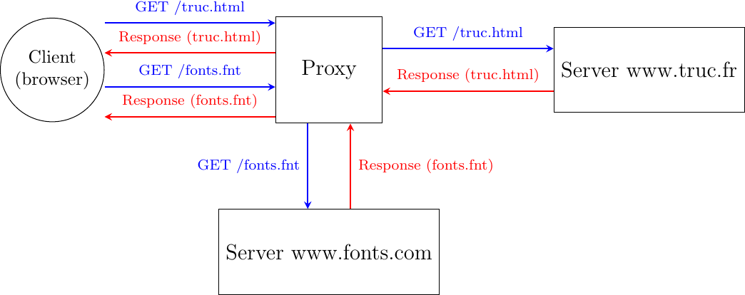
Caches can also be used inside the network. To understand their benefits, let us consider an SME with a dozen of employees that are connected to the Internet through a low-speed link. These employees often access similar web sites. Consider that Alice and Bob want to browse today’s local newspaper. Their browsers will both retrieve the newspaper’s website through the low bandwidth link and store the main documents in their cache. Unfortunately, the same information passes twice over the low-speed link. Some companies have deployed web proxies to cope with this problem. A web proxy is a server that resides in the enterprise network. All the employee’s browsers are configured to send their HTTP requests to this proxy. When such a proxy receives a request, it checks whether the content is already stored inside its own cache. If so, it returns it directly. Otherwise, the request is sent to the remote server and the information is stored in the proxy cache. By reducing the number of web objects that are exchanged over low-speed links, such proxies can significantly improve performance. Some companies also use them to control the websites that are contacted by their employees and sometimes block illegitimate accesses.
Proxies can also be located in front of servers. In this case, they are called reverse-proxies. Consider a dynamic web server that produces web pages by assembling information stored in different databases. When this server receives a request, it must send multiple queries to its databases and then create the HTML document. These queries and the creation of the HTML document take time and this limits the number of requests that our server can sustain. Many content providers would place a reverse proxy in front of such a server. The DNS servers are configured to point to the reverse proxy. Upon reception of a request, the reverse proxy first checks whether the response is already stored in its cache. If so, it can return it to the client without interacting with the official server. Otherwise, the reverse proxy contacts the server and then returns the response to the client.
These reverse proxies can also be used to spread the load among different servers. In the above example, consider that a server needs 10 milliseconds to process each request and that it must handle them sequentially. Such a server cannot support more than 100 requests per second. If the service becomes popular, then the content provider will need to deploy several servers. These servers could serve the same reverse proxy.
Note
Serving content from multiple servers
When a web user interacts with www.service.net, she expects that all the information comes from the www.service.net server. If the service is popular, there are probably tens, hundreds, thousands or more physical servers that support this service. Still, the user has the illusion that she is interacting with a single server. Several techniques have been deployed by content providers to scale web services. Consider a simple service that serves text documents from N different servers. There are different ways to architect such a service.
A first approach is to store all files on each physical server and rely on the DNS to distribute the load among them. Each physical server has its own IP address and when the DNS server receives a query for www.service.net, it returns the IP address of one of them. Some DNS servers use Round-Robin to return one of these IP addresses. Others measure the load of the physical servers and return the address of the less loaded one. Another possibility is to locate the physical servers in different regions and configure the DNS server to return the IP address of the server that is geographically closer to the client’s IP address.
A second approach is to rely on k reverse proxies and N-k servers. The servers store the content and the proxies cache the most frequently used files. The proxies can be geographically close to the clients while the servers can reside in the datacenters of the content provider. The DNS server can also distribute the load among the different proxies or return the geographically closest proxy. An important point to note about reverse proxies is that they receive HTTP requests from clients and send HTTP requests to the original servers that host the content. Several companies, usually called Content Distribution Networks, have deployed such reverse proxies throughout the world to cache web content next to the end-users. A good description of such a CDN may be found in [NSS2010].
A second way to improve the web performance is to reduce the time required to retrieve web objects. While the first web servers returned an HTML documents with possibly a few images, today’s rich web servers return one HTML document with associated style sheets, javascript code, images, fonts, … Some of these web objects come from the original server while others are hosted on different servers. Today, a typical web page contains almost 2 MBytes of data on average. The size of the web pages continues to grow according to statistics collected by httparchive.org as shown in Fig. 37. Web pages targeted to mobile devices are slightly smaller.
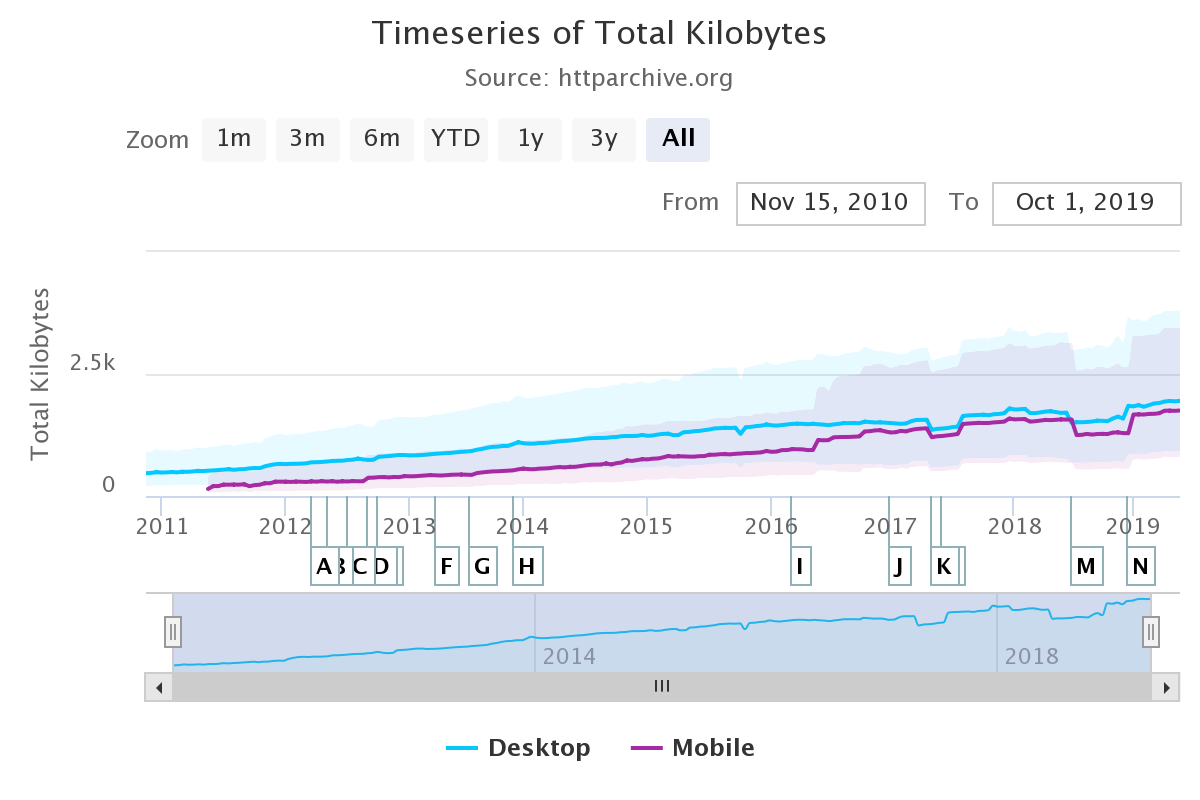
Fig. 37 Evolution of the size of the web pages (source: https://httparchive.org/reports/page-weight)#
A closer look at the average web page shows that it contains, on average, 27 KBytes of HTML, 120 KBytes of fonts, 60 KBytes of CSS information, almost 1 MBytes of images and more than 400 KBytes of javascript. Each of these web page requires about 70 different HTTP requests. In other words, a browser needs to send on average 70 requests to retrieve a complete web page.
Two directions have been explored to improve the delivery of these web pages. The first direction is to tune the HTTP protocol. The second approach is to change the entire network stack. This approach is discussed in the QUIC chapter.
One of the limitations of HTTP from a performance viewpoint is that the requests that are sent by a browser must be sequential. Typically, a browser requests the HTML page. Once the page has been retrieved, the browser parses it to identify all the objects that it references and requests them one after each other. The web page can only be displayed to the user once all the required web objects have been retrieved. This implies that the browser must wait until the reception of each response before sending the next request. Another possibility is to allow the browser to send multiple requests without waiting for their corresponding responses. This approach is called pipelining in RFC 7230.
To understand the benefits of pipelining, let us consider a simple but illustrative example. A client needs to retrieve 5 web objects that are each 100 bytes. The underlying transport connection has a 1 Gbps bandwidth but a one-way delay of 100 msec. A normal HTTP/1.x client would send the first request, wait 200 msec to receive the answer, then send another request… It would need one entire second to retrieve the five web objects. This is illustrated in Fig. 38.
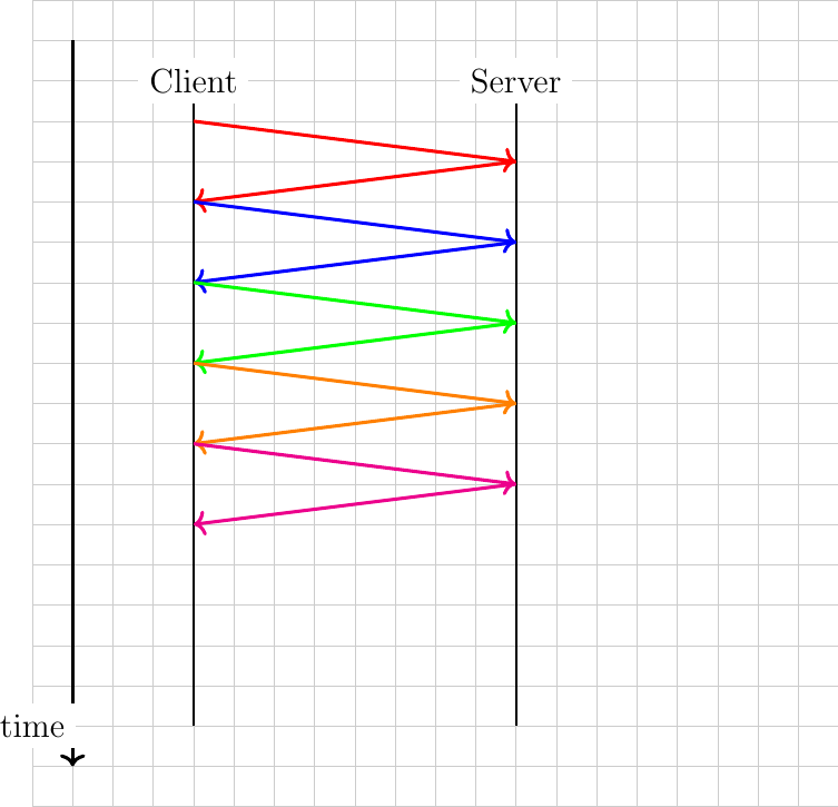
Fig. 38 A sequence of HTTP requests to a given server
With pipelining, the client sends the five requests immediately and receives the five responses after 200 msec. Fig. 39 illustrates the benefits of pipelining.
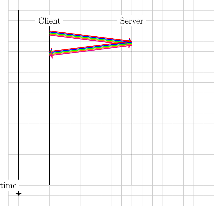
Fig. 39 A sequence of HTTP requests to a server with pipelining
However, as explained in RFC 7230, there is one important limitation to pipelining. It can only be used to serve HTTP requests that are idempotent, i.e. none of the requests must depend on any of the previous requests in the pipeline. It turned out that it was difficult for web browsers to correctly support this requirement and very few of them have implemented pipelining [19].
Another limitation of HTTP/1.1 is that all commands and parameters are encoded as ASCII strings. Using ASCII strings makes it easy to write simple clients or debug problems by observing packets. Unfortunately, the burden is placed on servers that need to include complex parsers that accept a wide range of partially compliant implementations. Furthermore, the flexibility of the ASCII encoding has enabled some classes of security attacks on servers [CWE444].
To cope with these two problems, the IETF HTTP working group developed version 2.0 of HTTP. HTTP/2.0 diverges from HTTP/1.1 in two important ways. First, HTTP/2.0 relies on binary encoding which is both more compact and easier to parse. Second, HTTP/2.0 supports multiple streams, which makes it possible to simultaneously transfer different web objects over a single transport connection. Furthermore, HTTP/2.0 also compresses the HTTP headers to reduce the amount of data transferred. This technique is described in RFC 7541 but is not discussed in this chapter.
Let us first examine how HTTP/2.0 structures the bytestream of the underlying connection.

Fig. 40 The HTTP/2.0 Frame header#
The information exchanged over an HTTP/2.0 session is composed of frames. A frame starts with a 9 bytes-long header that carries several types of information as shown in Fig. 40. The HTTP/2.0 frames have a variable length. The Length field of the header contains the length of the frame payload in bytes. As this field is encoded as a 24 bits field, an HTTP/2.0 frame cannot be longer than \(2^{24} -1\) bytes. It should be noted that RFC 7540 assumes a maximum size of \(2^{14}\) bytes, i.e. 16,384 bytes for the HTTP/2.0 frame payload unless a longer maximum frame length has been negotiated at the beginning of the session using the HTTP/2.0 Settings frame that will be described later. The next field of the frames header indicates the frame type. The first frame types are Data which contains data from web objects and Headers containing HTTP/2.0 headers. When a client retrieves a web object from a server, it always receives an HTTP/2.0 Headers frame followed by an HTTP/2.0 Data frame. The Headers frame information contains essentially the same HTTP headers as the ones supported by HTTP/1.1, but those are encoded by leveraging a data compression technique that minimizes the number of bytes required to transmit them.
Other frame types are described later. The Flags are used for some frame types and the R bit must be set to zero. The last important field of the HTTP/2.0 Frame header is the Stream Identifier. With HTTP/2.0, the bytestream of the underlying transport connection is divided in independent streams that are identified by an integer. The odd (resp. even) stream identifiers are managed by the client (resp. server). This enables the server (or the client) to multiplex data corresponding to different frames over a single bytestream.
This multiplexing capability is probably the most important feature of HTTP/2.0 from a performance viewpoint. To understand its benefits, let us consider a client that retrieves two web objects over a 1 Mbps connection. The two requests are sent together by the client. The first object is 125 bytes long, while the second is 12500 bytes long. In this case, the server will first return the first object as a single frame and the second will be sent in the subsequent frame.
Consider now that the first object is 12500 bytes long and the second 125 bytes long as shown in Fig. 41. With a 1 Mbps connection, this object will use the underlying connection during 100 milliseconds. The client will thus need to wait 100 milliseconds to retrieve the second object. This is the Head of Line (HoL) blocking problem that affects the performance of many web services. If the short web object is a javascript code that requests other web objects, its retrieval may be critical to display the retrieved web page.
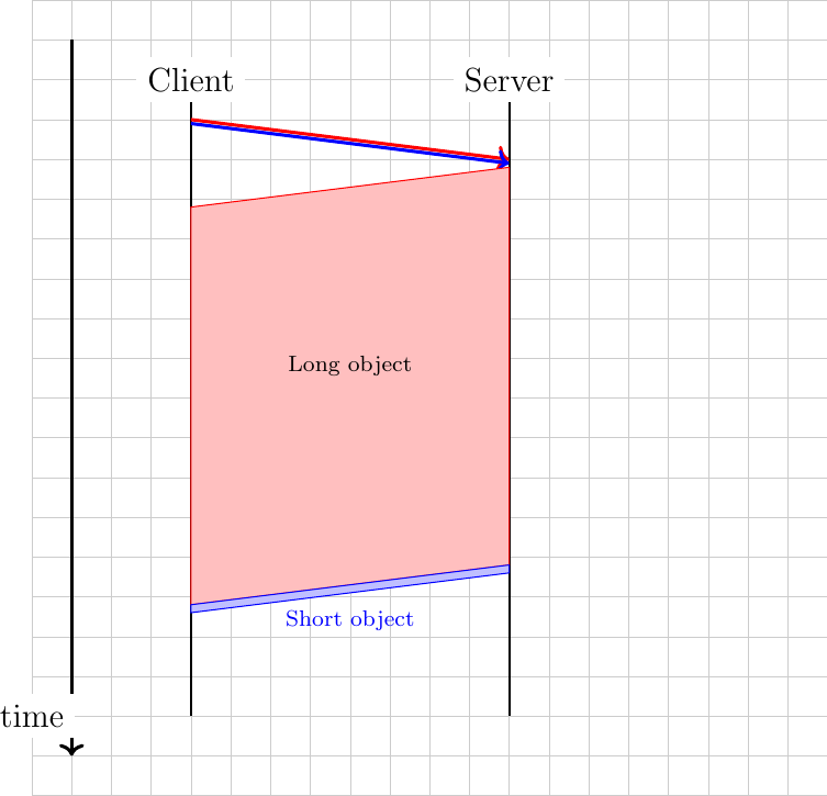
Fig. 41 Head-of-line blocking, a large response may deal a small one
With HTTP/2.0 frames, the server could send the first 1250 bytes of the long object during 10 milliseconds, then send a second frame that contains the short object during one millisecond and later send a longer frame that contains the remaining 11250 bytes of the long object. This is illustrated in Fig. 42. In this case, the client has received the short object after 10 milliseconds. Given the HTTP/2.0 streams, the transmission of long web objects does not anymore blocks the transmission of shorter ones.
The length of the HTTP/2.0 frames obviously affects how different web objects can be multiplexed over the underlying transport connection. If HTTP/2.0 frames are long, the overhead of the frame header is minimal, but long frames can block short web objects. On the other hand, if the frame length is small, then the overhead due to the HTTP/2.0 frame header could become significant.
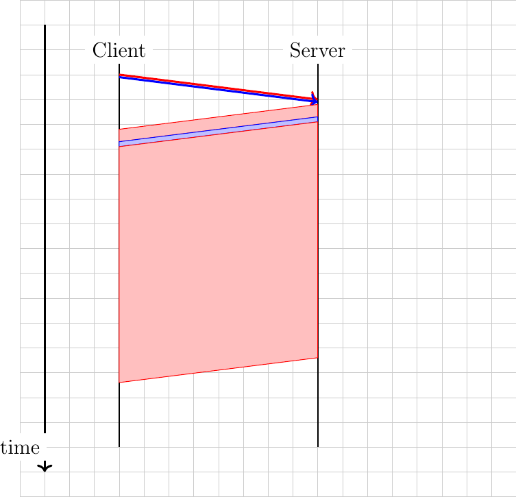
Fig. 42 The data from HTTP/2 frames can be interleaved to prevent head-of-line blocking
The HTTP/2.0 streams can provide performance benefits, but they also increase the complexity of the implementations since an HTTP/2.0 receiver must be able to simultaneously process frames that correspond to different web objects. This complexity mainly resides on the client side. The HTTP/2.0 protocol includes several techniques that enable clients to manage the utilization of the HTTP/2.0 session.
The first frame that a client sends over an HTTP/2.0 session is the Settings frame. This is a control frame that indicates some parameters that the client proposes for this session. Several of these parameters are defined in RFC 7540. The most important ones are probably the SETTINGS_MAX_FRAME_SIZE that specifies the maximum length of the HTTP/2.0 frames that this implementation supports and the SETTINGS_MAX_CONCURRENT_STREAMS that specifies the maximum number of parallel streams that this implementation can manage. The SETTINGS_MAX_FRAME_SIZE must be at least \(2^{14}\) bytes but can go up to \(2^{24} -1\) bytes. There is no minimum value for SETTINGS_MAX_CONCURRENT_STREAMS, but RFC 7540 recommends to support at least 100 different stream identifiers.
By using multiple streams, the server can multiplex different web objects over the same underlying transport connection. However, these objects are only sent in response to requests from clients. There are some situations where the server might know in advance that the client will request a given object. It could speedup the transfer by sending it before having received a client request. This is the push feature of HTTP/2.0. A server can independently push web objects to a client without having received any request. This feature can only be used by the server if the client has enabled it by sending SETTINGS_ENABLE_PUSH in its Settings frame. A classical use case for this push feature is to enable a server to automatically send an object which cannot be cached by the client, such as a dynamic javascript code, when another web object that references it is requested. However, measurement studies indicate that very few web servers seem to have adopted this feature [ZWH2018].
Another feature of HTTP/2.0 is that it is possible to assign different priorities to different streams. A high priority stream should carry more Data frames than a lower priority ones. The HTTP/2.0 specification defines Priority frames which can be used for this purpose.
As the server can send multiple objects at the same time, there is a risk of overloading the client buffers. To cope with this potential problem, HTTP/2.0 includes its own flow control mechanism. When an HTTP/2.0 session starts, a receiver agrees to receive up to 65,535 bytes over this connection (unless it has indicated a different initial window in its Settings frame). This limits the amount of data that a sender can transmit over the HTTP/2.0 session. The receiver can advertise a large receive window by sending a Window_Update frame at any time. This flow control mechanism can be applied to the entire connection or to a specific stream. In practice, using a small HTTP/2.0 window could severely limit the throughput over an HTTP/2.0 session.
HTTP/2.0 includes much more than what we have covered in this short introduction. There is for example a Ping frame that allows measuring the round-trip-time between a client and a server or the GoAway frame that indicates the termination of an HTTP/2.0 session. This frame contains an error code that indicates why the session has been terminated. Several error codes are defined in RFC 7540, including ENHANCE_YOUR_CALM that is used to indicate that the other endpoint exhibits an behavior that could cause excessive load.
Note
Detecting whether a server supports HTTP/2.0
HTTP/2.0 is a new version of the HTTP protocol that still uses port 80. When a client contacts an HTTP server, it must be able to determine whether it supports HTTP/1.x or HTTP/2.0. If the client sends a binary encoded HTTP/2.0 request to a server that only supports the ASCII encoded HTTP/1.x, it could cause problems on the server and even crash it. To minimize the risk of crashing HTTP/1.x servers, an HTTP/2.0 session starts like an HTTP/1.1 session and the first request contains the Connection, Upgrade and HTTP2-Settings headers. An example of such a request to upgrade the version of HTTP is shown below.
GET /robots.txt HTTP/1.1
Host: nghttp2.org
User-Agent: curl/7.52.1
Connection: Upgrade, HTTP2-Settings
Upgrade: h2c
HTTP2-Settings: AAMAAABkAARAAAAA
The HTTP2-Settings line contains the HTTP/2.0 settings frame that the client would server over an HTTP/2.0 session encoded in Base64. The server replies with a response that indicates that it has accepted to upgrade the connection to HTTP/2.0. A sample response is shown below.
HTTP/1.1 101 Switching Protocols
Connection: Upgrade
Upgrade: h2c
Finally, the client and the server need to confirm the utilization of HTTP/2.0. A client confirms this by sending the following Magic string PRI * HTTP/2.0rnrnSMrnrn or 0x505249202a20485454502f322e300d0a0d0a534d0d0a0d0a in hex. This string is followed by a SETTINGS frame. The server must send a possibly empty SETTINGS frame.
Remote Procedure Calls#
In the previous sections, we have described several protocols that enable humans to exchange messages and access to remote documents. This is not the only usage of computer networks and in many situations applications use the network to exchange information with other applications. When an application needs to perform a large computation on a host, it can sometimes be useful to request computations from other hosts. Many distributed systems have been built by distributing applications on different hosts and using Remote Procedure Calls as a basic building block.
In traditional programming languages, procedure calls allow programmers to better structure their code. Each procedure is identified by a name, a return type and a set of parameters. When a procedure is called, the current flow of program execution is diverted to execute the procedure. This procedure uses the provided parameters to perform its computation and returns one or more values. This programming model was designed with a single host in mind. In a nutshell, most programming languages support it as follows :
The caller places the values of the parameters at a location (register, stack, …) where the callee can access them
The caller transfers the control of execution to the callee’s procedure
The callee accesses the parameters and performs the requested computation
The callee places the return value(s) at a location (register, stack, …) where the caller can access them
The callee returns the control of execution to the caller’s
This model was developed with a single host in mind. How should it be modified if the caller and the callee are different hosts connected through a network ? Since the two hosts can be different, the two main problems are the fact they do not share the same memory and that they do not necessarily use the same representation for numbers, characters, … Let us examine how the five steps identified above can be supported through a network.
The first problem to be solved is how to transfer the information from the caller to the callee. This problem is not simple and includes two sub-problems. The first sub-problem is the encoding of the information. How to encode the values of the parameters so that they can be transferred correctly through the network ? The second problem is how to reach the callee through the network ? The callee is identified by a procedure name, but to use the transport service, we need to convert this name into an address and a port number.
Encoding data#
The encoding problem exists in a wide range of applications. In the previous sections, we have described how character-based encodings are used by email and HTTP. Although standard encoding techniques such as ASN.1 [Dubuisson2000] have been defined to cover most application needs, many applications have defined their specific encoding. Remote Procedure Call are no exception to this rule. The three most popular encoding methods are probably XDR RFC 1832 used by ONC-RPC RFC 1831, XML, used by XML-RPC and JSON RFC 4627.
The eXternal Data Representation (XDR) Standard, defined in RFC 1832 is an early specification that describes how information exchanged during Remote Procedure Calls should be encoded before being transmitted through a network. Since the transport service enables transferring a block of bytes (with the connectionless service) or a stream of bytes (by using the connection-oriented service), XDR maps each datatype onto a sequence of bytes. The caller encodes each data in the appropriate sequence and the callee decodes the received information. Here are a few examples extracted from RFC 1832 to illustrate how this encoding/decoding can be performed.
For basic data types, RFC 1832 simply maps their representation into a sequence of bytes. For example a 32 bits integer is transmitted as shown in Fig. 43 (with the most significant byte first, which corresponds to big-endian encoding).

Fig. 43 XDR representation of a 32 bits integer#
XDR also supports 64 bits integers and booleans. The booleans are mapped onto integers (0 for false and 1 for true). For the floating point numbers, the encoding defined in the IEEE standard is used. In the representation, the first bit (S) is the sign (0 represents positive). The next 11 bits represent the exponent of the number (E), in base 2, and the remaining 52 bits are the fractional part of the number (F). The floating point number that corresponds to this representation is \((-1)^{S} \times 2^{E-1023} \times 1.F\). XDR also allows encoding complex data types. A first example is the string of bytes. A string of bytes is composed of two parts : a length (encoded as an integer) and a sequence of bytes. For performance reasons, the encoding of a string is aligned to 32 bits boundaries. This implies that some padding bytes may be inserted during the encoding operation is the length of the string is not a multiple of 4. The structure of the string is shown below (source RFC 1832).

Fig. 44 XDR representation of a floating point number#
In some situations, it is necessary to encode fixed or variable length arrays. XDR RFC 1832 supports such arrays. For example, the encoding in Fig. 45 corresponds to an array containing n elements. The encoded representation starts with an integer that contains the number of elements and follows with all elements in sequence.

Fig. 45 XDR representation of an array#
XDR also supports the definition of unions, structures, … Additional details are provided in RFC 1832.
A second popular method to encode data is the JavaScript Object Notation (JSON). This syntax was initially defined to allow applications written in JavaScript to exchange data, but it has now wider usages. JSON RFC 4627 is a text-based representation. The simplest data type is the integer. It is represented as a sequence of digits in ASCII. Strings can also be encoding by using JSON. A JSON string always starts and ends with a quote character (”) as in the C language. As in the C language, some characters (like “ or \) must be escaped if they appear in a string. RFC 4627 describes this in details. Booleans are also supported by using the strings false and true. Like XDR, JSON supports more complex data types. A structure or object is defined as a comma separated list of elements enclosed in curly brackets. RFC 4627 provides the following example as an illustration.
{
   "Image": {
       "Width":  800,
       "Height": 600,
       "Title":  "View from 15th Floor",
       "Thumbnail": {
           "Url":    "http://www.example.com/image/481989943",
           "Height": 125,
           "Width":  100
       },
       "ID": 1234
     }
}
This object has one field named Image. It has five attributes. The first one, Width, is an integer set to 800. The third one is a string. The fourth attribute, Thumbnail is also an object composed of three different attributes, one string and two integers. JSON can also be used to encode arrays or lists. In this case, square brackets are used as delimiters. The snippet below shows an array which contains the prime integers that are smaller than ten.
{
  "Primes" : [ 2, 3, 5, 7 ]
}
Compared with XDR, the main advantage of JSON is that the transfer syntax is easily readable by a human. However, this comes at the expense of a less compact encoding. Some data encoded in JSON will usually take more space than when it is encoded with XDR. More compact encoding schemes have been defined, see e.g. [BH2013] and the references therein.
Reaching the callee#
The second sub-problem is how to reach the callee. A simple solution to this problem is to make sure that the callee listens on a specific port on the remote machine and then exchange information with this server process. This is the solution chosen for JSON-RPC [JSON-RPC2]. JSON-RPC can be used over the connectionless or the connection-oriented transport service. A JSON-RPC request contains the following fields:
jsonrpc: a string indicating the version of the protocol used. This is important to allow the protocol to evolve in the future.
method: a string that contains the name of the procedure which is invoked
params: a structure that contains the values of the parameters that are passed to the method
id: an identifier chosen by the caller
The JSON-RPC is encoded as a JSON object. For example, the example below shows an invocation of a method called sum with 1 and 3 as parameters.
{ "jsonrpc": "2.0", "method": "sum", "params": [1, 3], "id": 1 }
Upon reception of this JSON structure, the callee parses the object, locates the corresponding method and passes the parameters. This method returns a response which is also encoded as a JSON structure. This response contains the following fields:
jsonrpc: a string indicating the version of the protocol used to encode the response
id: the same identifier as the identifier chosen by the caller
result: if the request succeeded, this member contains the result of the request (in our example, value 4).
error: if the method called does not exist or its execution causes an error, the result element will be replaced by an error element which contains the following members :
code: a number that indicates the type of error. Several error codes are defined in [JSON-RPC2]. For example, -32700 indicates an error in parsing the request, -32602 indicates invalid parameters and -32601 indicates that the method could not be found on the server. Other error codes are listed in [JSON-RPC2].
message: a string (limited to one sentence) that provides a short description of the error.
data: an optional field that provides additional information about the error.
Coming back to our example with the call for the sum procedure, it would return the following JSON structure.
{ "jsonrpc": "2.0", "result": 4, "id": 1 }
If the sum method is not implemented on the server, it would reply with the following response.
{ "jsonrpc": "2.0", "error": {"code": -32601, "message": "Method not found"}, "id": "1" }
The id field, which is present in the request and the response plays the same role as the identifier field in the DNS message. It allows the caller to match the response with the request that it sent. This id is very important when JSON-RPC is used over the connectionless transport service which is unreliable. If a request is sent, it may need to be retransmitted and it is possible that a callee will receive twice the same request (e.g. if the response for the first request was lost). In the DNS, when a request is lost, it can be retransmitted without causing any difficulty. However with remote procedure calls in general, losses can cause some problems. Consider a method which is used to deposit money on a bank account. If the request is lost, it will be retransmitted and the deposit will be eventually performed. However, if the response is lost, the caller will also retransmit its request. This request will be received by the callee that will deposit the money again. To prevent this problem from affecting the application, either the programmer must ensure that the remote procedures that it calls can be safely called multiple times or the application must verify whether the request has been transmitted earlier. In most deployments, the programmers use remote methods that can be safely called multiple times without breaking the application logic.
ONC-RPC uses a more complex method to allow a caller to reach the callee. On a host, server processes can run on different ports and given the limited number of port values (\(2^{16}\) per host on the Internet), it is impossible to reserve one port number for each method. The solution used in ONC-RPC RFC 1831 is to use a special method which is called the portmapper RFC 1833. The portmapper is a kind of directory that runs on a server that hosts methods. The portmapper runs on a standard port (111 for ONC-RPC RFC 1833). A server process that implements a method registers its method on the local portmapper. When a caller needs to call a method on a remote server, it first contacts the portmapper to obtain the port number of the server process which implements the method. The response from the portmapper allows it to directly contact the server process which implements the method.
Footnotes